29
9 Double shunt layout function
This enables the manual or auto-
matic transfer of the load from a
source chosen as a normal power
supply (cable 1) to a second source
called a "backup" (cable 2).
The double shunt layout function
comprises two IS each of which is
equipped with a C410M mechanical
control mechanism (without mecha-
nical latching) or C440M (with dou-
ble mechanical latching), and a
voltage detection relay of the IPT
type.
1 − The double shunt layout func-
tion without any detection of an HV
fault comprises: 1 automatic chan-
geover box with four 12 V batteries,
2 cables marked Cable A and
Cable B of 5 or 10 metres each.
2 − The double shunt layout func-
tion with detection of an HV fault
comprises: 1 PASA automatic
changeover box with four 12 V bat-
teries, 2 cables marked Cable A
and Cable B of 5 or 10 metres
each, 6 opening rings equipped
with connectors, 2 cables for the
connection of the rings equipped
with connectors of 7 or 12 metres
each.
For the installation of the
automatic changeover switch,
refer to the instruction notice
"PASA Box" Ref. AREVA N° 896 A.
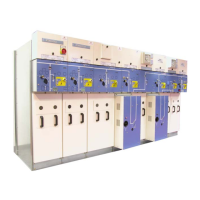
F Schematic diagram for the
double shunt function without
fault detection.
Voltage
detection
relay
Automatic
changeover
switch
MM
Voltage
detection
relay
Cable 1 Cable 2
F Connection of the control to the
PASA box, delivered
systematically in UFA.
Low voltage box with
neutralization switch
Connection
terminal to
automatic
changeover switch
Packet containing
some self−stick
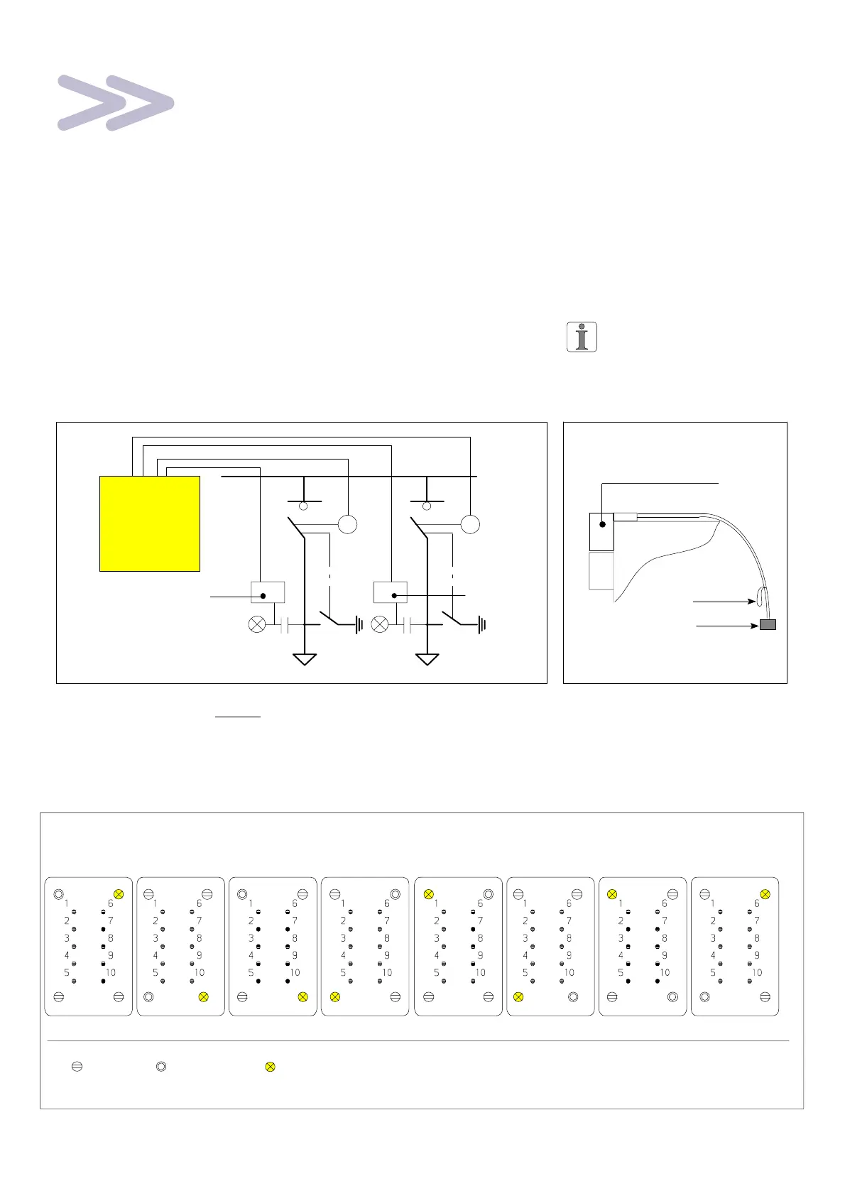
9.1 Foolproofing of the remote control connector [Public Distribution]
UFA UFB UFC UFD
Screw Socket
Foolproofing is made by journals
screwed into the female connector
Pin
10 pin male connector − Type H.an 10A (seen from pin side)
UFE UFF UFG UFH