6
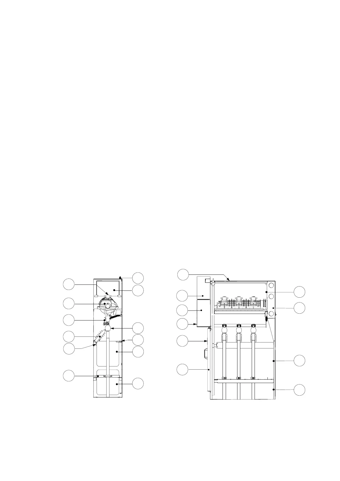
3.3 Presentation of the Functional Units
IS (Switch−Disconnector)
0 Key
−1 Busbar connection plates
−2 ISR switch−disconnector
−3 Upstream Earthing Switch
−4 Upper fuse support shell
−5 Cable connections shell
−6 MV Fuse
−7 Capacitive insulator
−8 Lower fuse holder shell
−9 Downstream Earthing Switch
−10 Base plate in 4 elements
−11 LV casing
−12 Exhaust shaft
−13 Overpressure valves
−14 Earthing bar connection point
−15 Access panel to the busbars
−16 Mechanical control mechanism for the
switch
1
2
7
5
3
13
16
11
19
20
21
10
12
14
18
13
22
13
13
13
−17 Circuit breaker mechanical control mechanism
(BLR)
−18 Voltage presence luminous indicators or interface
for Voltage Detection System
−19 Inspection window for checking the earthing
switch position
−20 Earthing pin for installation of earthing block
−21 Access panel to the cable compartment
−22 ES location (LV capacitors)
−23 Voltage transformers
−24 Auxiliary contacts
−25 Current transformers
−26 Cable connection lugs
−27 FP circuit breaker with interruption under SF6 gas
−28 ISR locked in ‘Open’ position
−29 Upper plugging−in clamps
−30 Lower plugging−in clamps
−31 HV Fuse
13
15