6.4 Attaching the Monitor Mount
CAUTION!
Ensure that Cam Pwr and STAB Pwr are switched OFF.!
!
NOTICE!
Due to the fact that there are small differences and
tolerances in the Gimbal handle diameter, you may need to
place some Tape around the Gimbal handle to secure the
mount. This tape also helps prevent the Gimbal handle from
scratches.
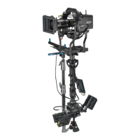
The shown position is the best starting point. Keep the
clamp section close to the curved part of the handle, this will
give enough clearance to ensure that the base of the
TRINITY will not hit the monitor accidentally.
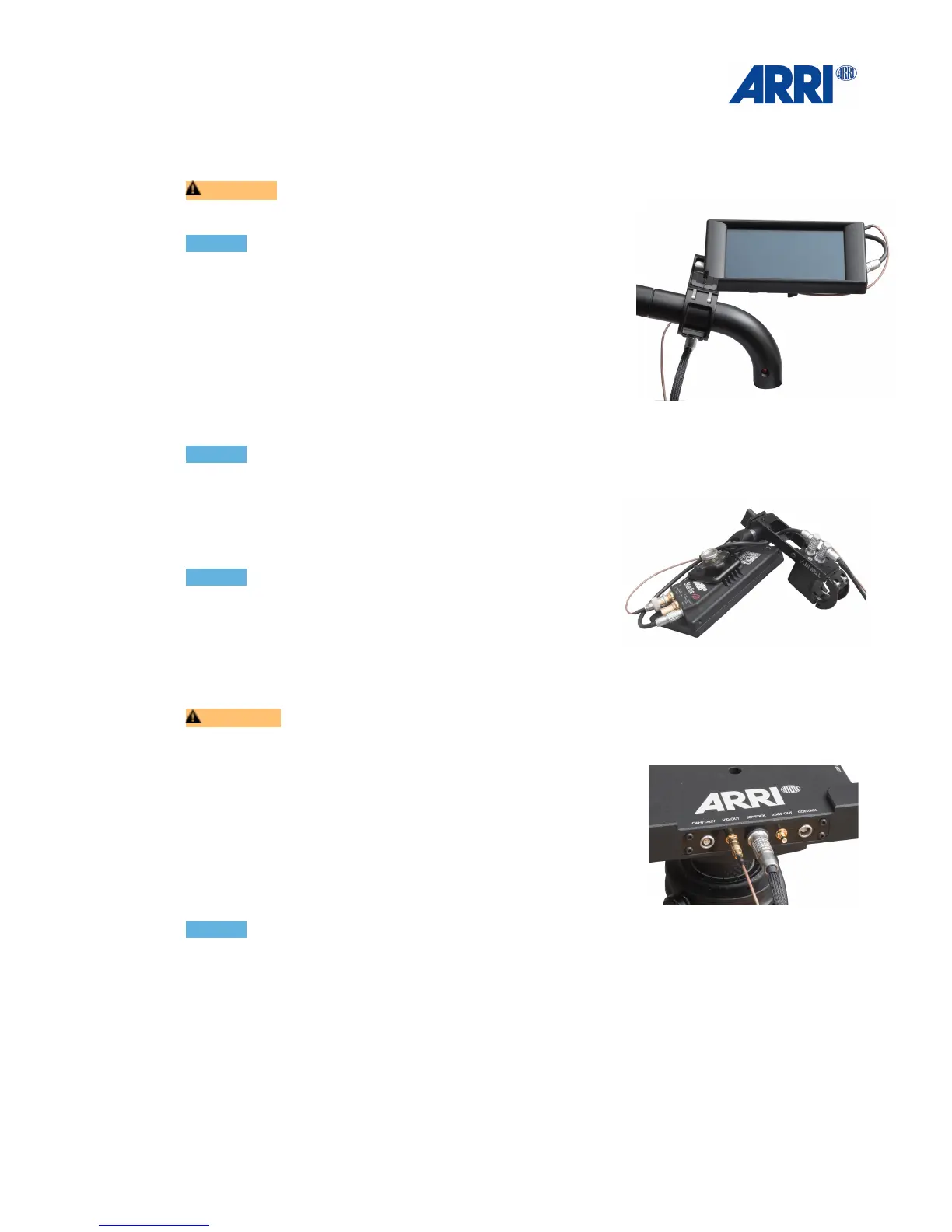
NOTICE!
Make sure that the connectors are always pointing away !
from the TRINITY Joystick / Monitor Mount.!
!
Connect the straight 5pin LEMO 0B with the ARRI
Starlight Power connector.!
!
NOTICE!
The system also includes a 2 pin Lemo 0B power cable for
standard Starlight.!
!
Connect the Joystick BNC cable to Video In.
Connect the 90°elbow 5pin LEMO with 5pin socket at the bottom of the Joystick housing.!
!
CAUTION !
Ensure that all cables are securely routed and cannot be accidentally damaged.!
!
Connect the 90°elbow 7pin LEMO with 7pin socket at the
bottom of the Joystick housing.
Connect the 7pin LEMO 1B Joystick Main cable with the
Joystick socket at the base of the TRINITY.!
!
Connect the Joystick BNC cable to Video Out.!
!
!
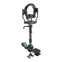
NOTICE!
To get a video signal straight from the Camera to the Monitor, the Camera HD signal has to be
connected to HD2 on the Trinity ring and the Joystick BNC cable has to be connected to Video
Out on the base of the Trinity.!
!
HD 1 is the “Clean Feed” video signal. This video signal goes down through the Center Post
to the HD1 BNC connector at the Top Stage on the bottom of the system. This video signal
can be used for Video Transmitters and accessories. This signal can also be looped back up
through the Center Post for a clean feed at the top of the Trinity by using HD 2 on the Top
Stage. This looped signal than will be available at the Loop Out at the front of the TRINITY
base.!
This video line can also used as a backup video line.