CYC5000 User Guide www.arrow.com
Page | 35 March 2023
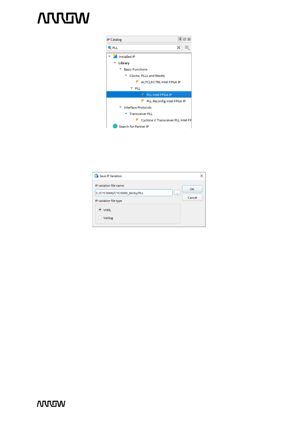
5.2.4.2 Click “Add”. When the Save IP Variation window appears, enter the file name variation
as PLL and select VHDL (Verilog can be used as well). Both Verilog and VHDL schematics
will be created.
5.2.4.3 Click “OK”.
The next step is to configure the PLL component that we just named.
5.2.4.4 On the General tab, make sure that “Integer-N PLL“ is set for PLL mode and enter the
PLL reference clock frequency to match the clock input on the CYC5000 Board. We
have 12 MHz clock signal coming into the FPGA, so we will use 12MHz for the Reference
Clock Frequency.
5.2.4.5 Simplify the PLL by disabling ‘locked output port’.
5.2.4.6 Check if the number of clocks set to 1 and set the desired frequency to 20MHz for
outclk0. For simplification, there are two inputs to the PLL (12 MHz and Reset), and one
output of the PLL (20 MHz)
The setting should look like this: