CYC5000 User Guide www.arrow.com
Page | 36 March 2023
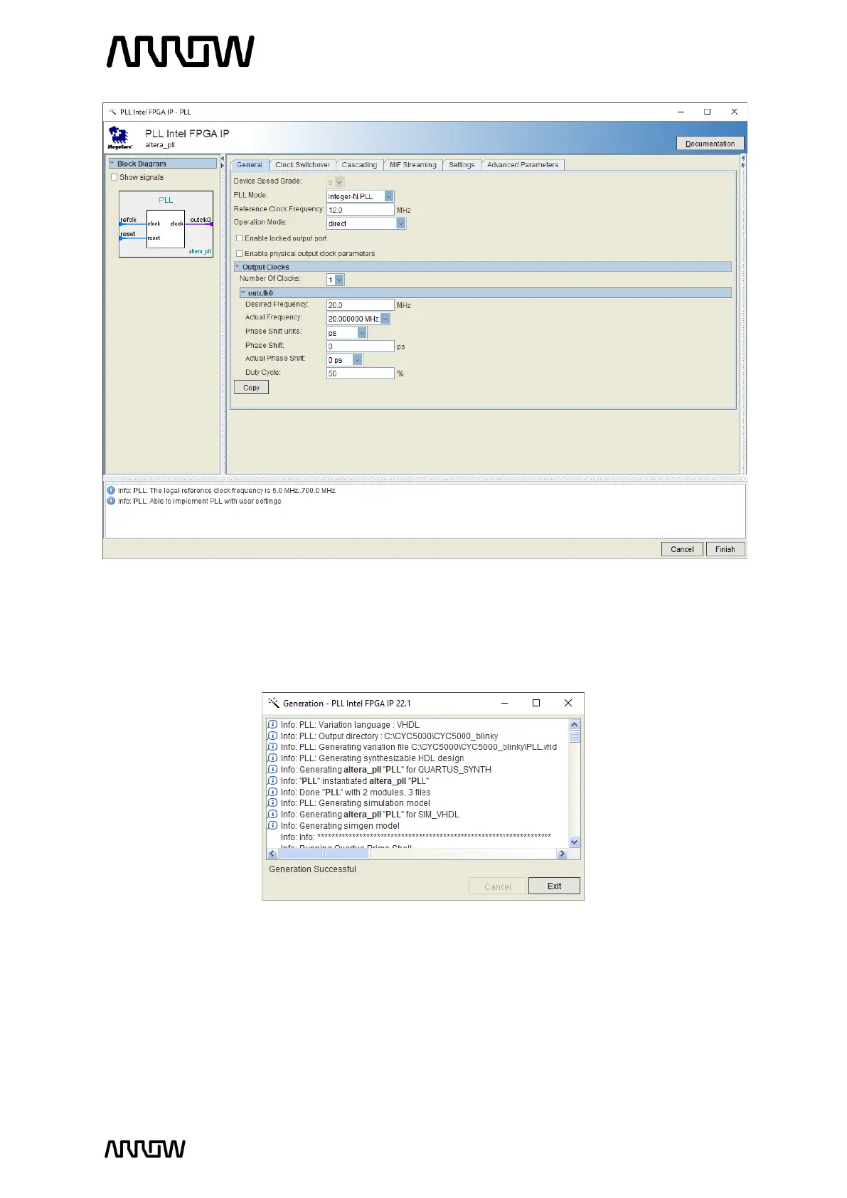
5.2.4.7 Leave the rest as default and click “Finish”. The PLL (1
st
component) will now be created.
5.2.4.8 If the PLL has been generated correctly, the following window will appear.
Click “Exit” to close it.
5.2.5 Create and Configure the Counter
The next step is to create the counter which will drive the LEDs on the CYC5000 board.
5.2.5.1 To create this counter, select the IP Catalog and expand the Basic Functions →
Arithmetic and select the LPM_COUNTER or type “counter” in the search field.