CYC5000 User Guide www.arrow.com
Page | 10 March 2023
Connections and Peripherals of the CYC5000
Board
3.1 Board Status Elements
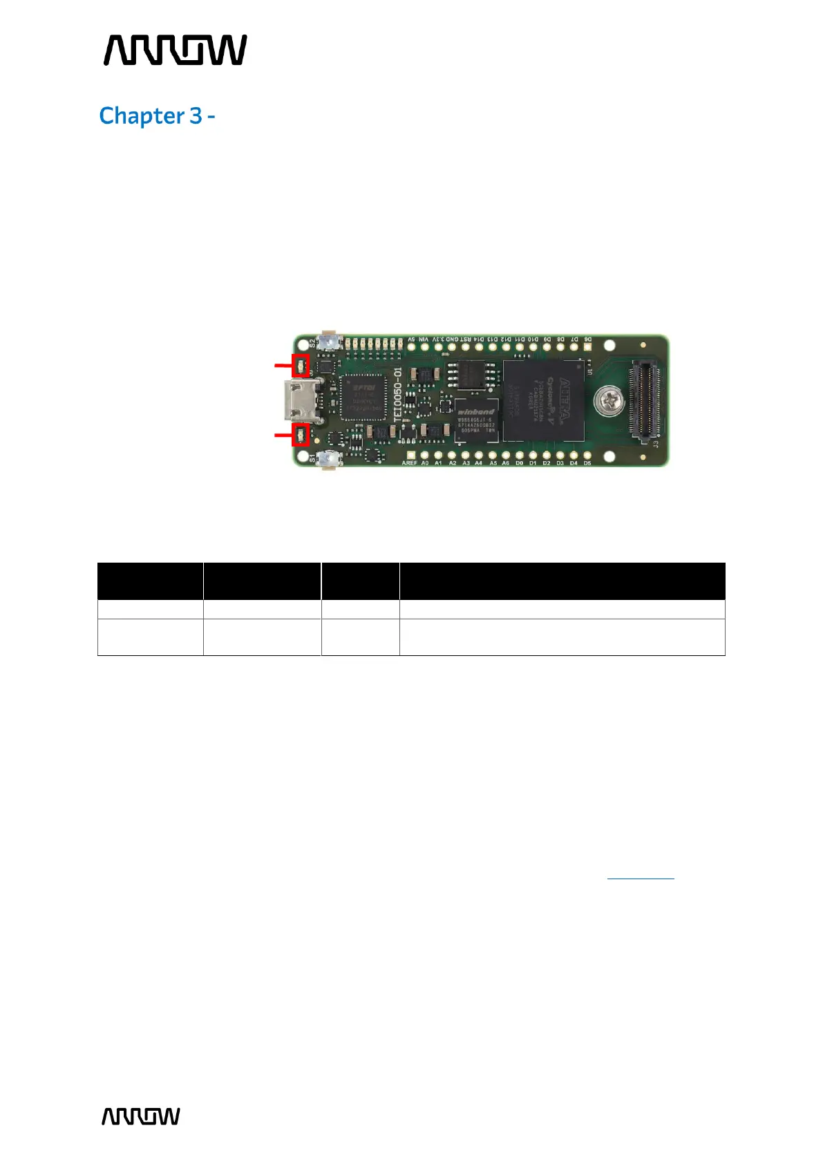
In addition to the 8 user LEDs that the FPGA can control, there are 2 additional board-specific
status LEDs that can indicate the status of the board.
On when 3.3V power is active
Off when configuration data was loaded to
Cyclone V device without error
3.2 Clock Circuitry
The external clock of the system can be seen in Figure 4. The default clock (CLK12M) is at 12MHz
and is connected and driving the FPGA’s user logic and the Arrow USB Programmer2. There is an
optional clock input from CRUVI HS Connector, where you can add another preferred clock
source to the FPGA (REFCLK). Both clock signals drive the internal PLLs of the FPGA.
For more information on clocks and PLLs of the Cyclone V, please refer to this document.
Figure 3 – Position of Indication LEDs