2 of 5
P/N PM000117A • Rev. 2 • ISS 09MAY2017
Mounting the Backplate Spacer Without a Backbox
When no backbox is available, mount the light directly to a
flat wall surface using four screws suitable for the wall type.
Cable wires should enter and leave the light’s housing
through the hole in the center of the backplate spacer, or
through the knock-outs at the top and sides of the spacer.
Consider where the connecting cables are located. If the
connecting cables run inside the wall, locate the spacer over
the hole where the cables extend from the wall. If the
connecting cables run in a channel outside the wall, locate
the spacer below and to the right or left of the channel,
where the cables exit the channel. The cables should enter
through the knockout holes in the spacer.
Do not distort or twist the spacer when mounting it to a wall.
If the spacer is distorted, the light will not fit properly and
may fall off. To prevent distortion, only mount the spacer on
a smooth and level surface. Do not over-tighten the screws.
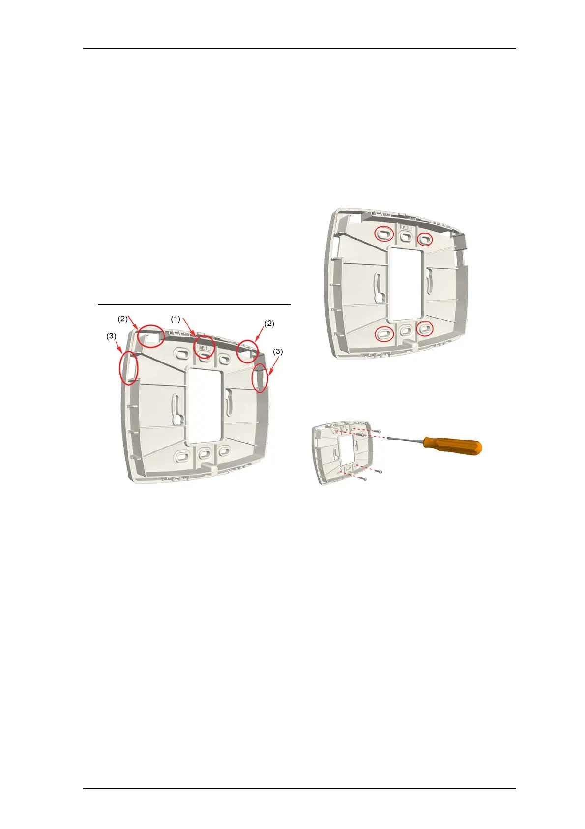
Backplate spacer with directional arrow and knockouts
Legend
(1) Directional arrow indicator
(2) Top knockouts
(3) Side knockouts
To remove the knockouts:
1. Determine how much space will be needed to
accommodate the cables entering the light’s housing, and
then choose which knockouts to remove from the spacer.
2. Remove the knockouts from the top or sides of the spacer.
See the figure above, items 2 and 3.
3. Using a cutter or pliers, carefully remove the excess plastic
from the knockouts.
To mount backplate spacer on a wall:
1. Place the backplate spacer against a flat wall and orient
it so that arrow printed on the inside of the spacer is
pointing up and that the spacer is level. Use a leveling
device to check, if necessary.
2. Using the spacer as a template, mark four holes for the
screws using the fitting holes located in the spacer, as
shown below.
3. Remove the spacer and drill holes for the screws that will
be used, such as wood, concrete, drywall screws, or
screws with anchors.
4. Place the spacer over the holes, insert the screws, and
then tighten.
5. If the cables come through the wall, pull the cables
through the hole in the center of the spacer.
-or-
If the cables come through a channel attached to the
outside of the wall, use the knock outs at the top and
sides of the spacer.
NUCL4P-H Light Module Connectors and Jumper
The light module uses two 8-pole connector terminals to
connect to the passive room buses. Each connector (not
included) is a screwless, spring-cage terminal with two
connection points. The terminals connect to the primary
and secondary room buses. The light module also includes a
jumper for selecting either a white or a blue LED in the
fourth section.