2 of 3 P/N PM000110A • REV 1 • ISS 14OCT2016
Wall-Mounted Display
Installing the handset cradle for a wall-mounted display
To install the optional handset accessory (NGHSDSP-A) to the touch
screen display:
1. Align the bracket attachment holes with the four holes on the
back of the touch screen display.
2. Locate screws in handset kit and insert screws into the four holes
and tighten each screw individually in a clockwise motion with
screwdriver until all four screws are secure.
Touch screen display with optional handset accessory
Installing the mounting plate onto a back box
To install the mounting plate onto a back box:
1. Hold the mounting plate against the back box.
2. Align the holes of the mounting plate with the holes of the back
box.
Note: This will vary depending on the type of back box.
3. Locate screws included in the mounting plate package and insert
screws into the holes of the mounting plate.
4. Secure the screws with a Phillips head screwdriver by turning
clockwise.
Wiring for wall-mounted display
The touch screen display connects to the Telligence system through
a Power over Ethernet (PoE) switch using a Cat 5/5e cable with RJ-
45 connectors (Cat 6/7 cable will work electrically but may be too
stiff for some back boxes).
Notes:
1. All US and Canada installations, require powering from the HC-
IPSWITCH8 or other E23929 listed PoE Switch.
2. For non-US or Canada installations, a locally sourced PoE switch
or power injector with EMC Class B rating must be used.
3. All wall mount installations require the ferrite core for Class B
compliance.
To connect a touch screen display:
1. Connect a Cat 5/5e cable to the back of the touchscreen display.
2. Clamp the round ferrite core provided with the NGWDSP-H on the
Cat 5/5e cable 1 inch from the PoE jack on the back of the
touchscreen display.
3. Connect the Cat 5/5e cable from the PoE jack on the device to the
IPSwitch8 or the PoE switch.
4. Connect the handset cord to the TEL connector and then to the
jack at the bottom of the handset. Place handset in cradle.
Note: When the optional handset is used, connect the handset
cord to the TEL connector, making sure to weave the cord
through the strain relief channel on the unit backside.
5. Hold the display against the wall above the secured mounting
plate and slide the display down into the mounting plate until
it clicks into place.
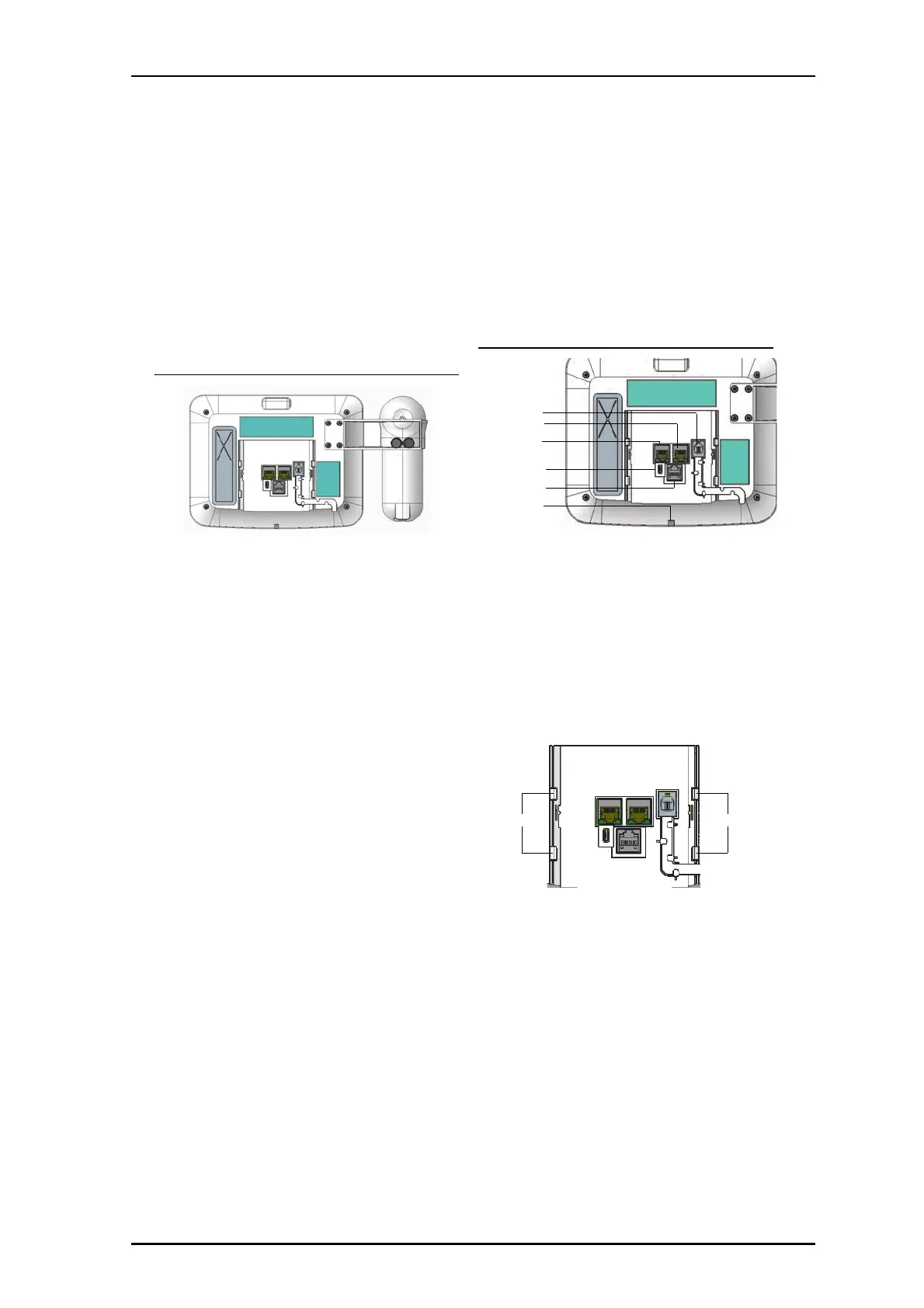
Touch screen display wiring connections
Note: If the warranty seal is broken, the warranty will be void.
Desktop Display
Installing a desktop display
To install a touch screen display onto the desktop pedestal:
1. Connect the pedestal Cat 5/5e cable to the PoE port on the back
of the touch screen display.
2. Connect the pedestal phone cable to the TEL port on the back
of the display.
3. Hold the touch screen display slightly above pedestal and align
tabs on the back of display with tabs on the pedestal.
Touch screen display tabs locations
4. Slide the touch screen display down onto the pedestal until the
unit clicks into place.
Note: Ensure the bottom tabs are secured before releasing grip
on the touch screen display.
Wiring for desktop display
The desktop display connects to the Telligence system through a
Power over Ethernet (PoE) switch using a Cat 5/5e cable with RJ-
45 connectors and a jack at the base of the pedestal.
TEL (Handset)
RJ22
PoE
AUX
Room
USB
(Reserved)
Warranty seal