P/N PM000199A • Rev. 2 • ISS 25MAY2017
3 of 5
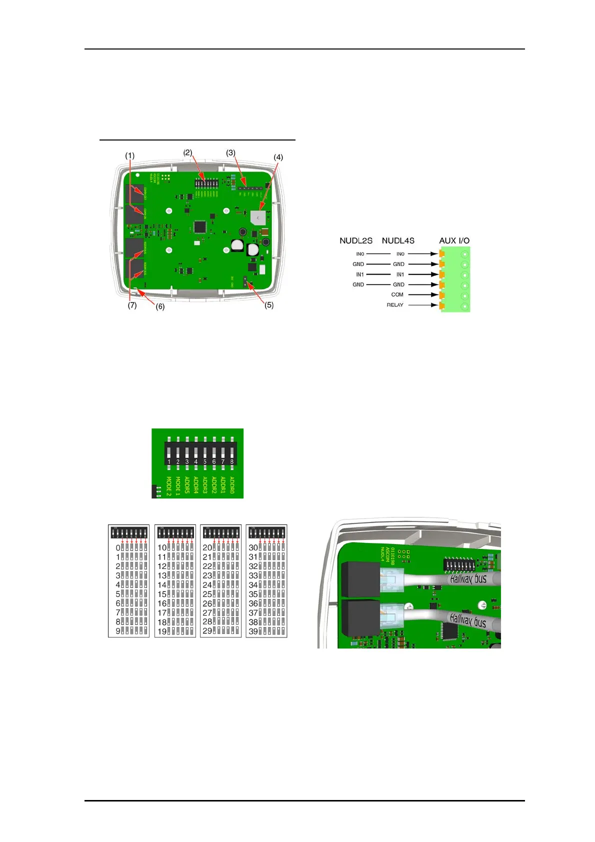
NUDL-series dome light connections
Legend
(1) 2x RJ-45 connection to hallway bus
(2) DIP switches for hallway bus addressing
(3) Auxiliary I/O terminal for auxiliary inputs
(4) Buzzer
(5) 36VDC power connection
(6) Status LED
(7) 2x RJ-45 connections to active room buses
To set the DIP switches:
1. Set the DIP switches to the address chosen for the active
hallway device.
Use the address table below to determine the correction
positions (ON or OFF) for the DIP switches.
mp
2. Using a small screwdriver, gently slide the switch up for
“ON” or slide it down for “OFF.”
Note: DIP switches 1 and 2 are mode switches and must
remain in their OFF positions.
To terminate a 4-pole or 6-pole connector for an auxiliary
I/O cable:
1. Terminate the auxiliary I/O cable with a 4-pole connector,
or a 6-pole connector, as required. (Connectors not
included.)
Note: The NUDL2-series dome lights do not have RELAY
or COM.
To connect a dome light:
1. Set the dome light’s DIP switches according to your
installation’s bus addressing scheme. See the figure
“NUDL-series dome light connections”, item 1.
Note: If your installation does not require DIP switches,
skip this step and use the Software Configuration Tool.
The DIP switches must remain in their OFF position.
2. If you are connecting an auxiliary I/O to the dome light,
terminate the wires from the auxiliary device to the proper
terminals on the 4- or 6-pole connector; otherwise, skip
this step. Ensure the connector is seated properly on the
terminal pins. See the figure “NUDL-series dome light
connections”, item 3.
3. Insert the RJ-45 connector from the hallway bus (IN) into
the COMM IN jack on the back of the light, and then insert
the RJ-45 connector to the next device on the hallway bus
(OUT) into the COMM OUT jack.