P/N PM000192A • Rev. .0 • ISS 23JUN2017
3 of 3
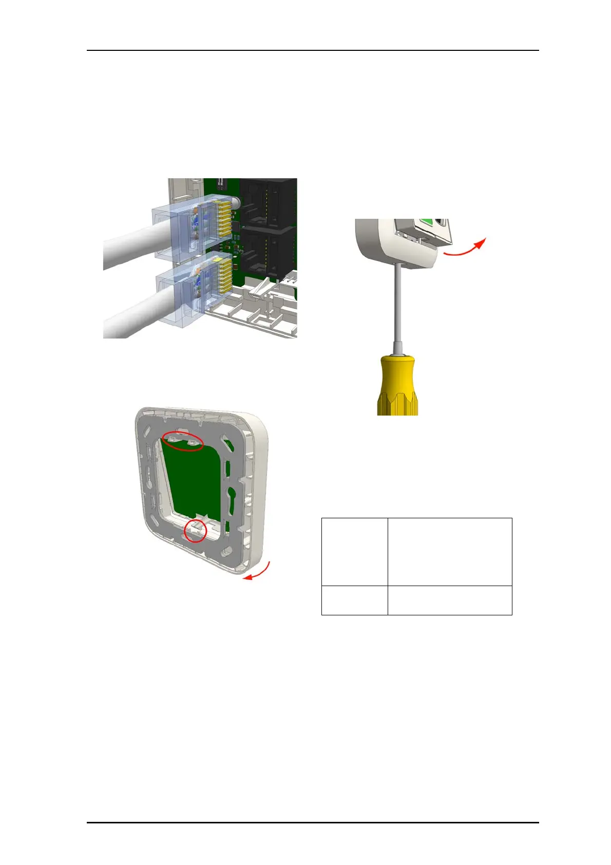
5. Insert the RJ-45 room bus connector into the first jack, and
then insert the next connector (to the next module) into
the other jack, as shown below. (IN from the previous
module and OUT to the next module).
To attach the module on the adapter:
1. Place the module against the frame, ensuring that the
module is facing up.
2. Place the module’s upper snap fasteners against the upper
edge of the adapter.
3. Press the module firmly against the adapter so that the
module’s bottom fasteners snap closed on the adapter.
See previous figure.
Removal
When separating the module from an adapter or spacer, use
a screwdriver with a blade that is approximately 6mm wide.
To remove the module from a backbox or spacer:
1. Insert the 6mm flat blade screwdriver into the slot at the
bottom of the module between the faceplate and the
adapter.
2. Gently push the 6mm flat blade screwdriver until the
module releases from the adapter.
Caution: Do not insert the screwdriver into the bottom
corner of the frame, as this may damage the frame or
module.
3. Remove the module from the adapter.
Specifications
Wire/terminations
Cat 5/5e/6/7 U/UTP with RJ-45
connectors.
Note: Cat 6/7 cable will work electri-
cally but may be too stiff for some
back boxes.
4 pole connector
6 pole connector
Compatible
electrical boxes
European Union, United Kingdom:
Standard plastic or metal back box
with mounting holes: 60mm (2.36”),