2 of 4
P/N PM000116A • Rev. 1 • ISS 25MAY2017
Consider where the connecting cables are located. If the
cables are run inside the wall, locate the device over the hole
where the cables extend from the wall. If the connecting
cables are run in a channel outside the wall, locate the device
below and to the right or left of the channel, where the cables
exit the channel. The cables should enter though the
knockout holes in the device’s backplate.
Do not distort or twist the backplate when mounting it to a
wall. If the backplate is distorted, the light will not fit
properly and may fall off. To prevent distortion, only mount
the backplate on a smooth and level surface. Do not over-
tighten the screws.
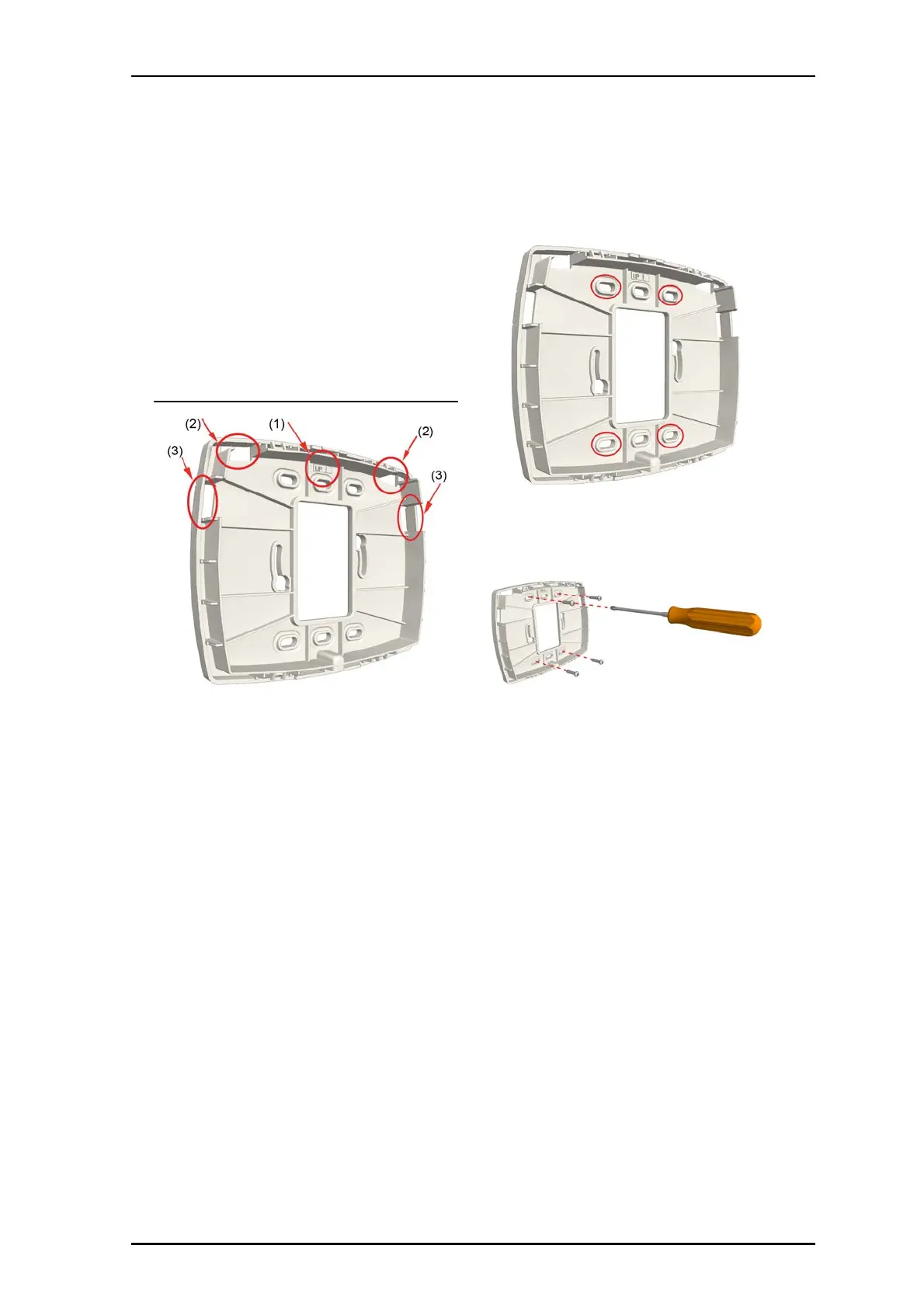
Backplate spacer with directional arrow and knockouts
Legend
(1) Directional arrow indicator
(2) Top knockouts
(3) Side knockouts
To remove the knockouts:
1. Determine how much space will be needed to
accommodate the cables entering the light’s housing, and
then choose which knockouts to remove.
2. Removed from the top or sides of the backplate. See the
figure above, items 2 and 3.
3. Using a cutter or pliers, carefully remove the excess plastic
from the knockouts.
To mount backplate spacer on a wall:
1. Place the backplate spacer against a flat wall and orient it
so that arrow (printed on the inside of the backplate) is
pointing up and that the backplate is level. Use a leveling
device to check, if necessary.
2. Using the backplate as a template, mark four holes for
the screws using the fitting holes located in the
backplate, as shown below.
3. Remove the backplate and drill holes for the screws that
will be used, such as wood, concrete, drywall screws, or
screws with anchors.
4. Place the backplate over the holes, insert the screws, and
then tighten.
5. If the cables come through the wall, pull the cables
through the hole in the center of the backplate spacer.
-or-
If the cables come through a channel attached to the
outside of the wall, use the knock outs at the top and
sides of the backplate spacer.
Connecting Cables and Setting DIP Switches
The NUCL4-H light provides RJ-45 jacks for connecting the
light to the room bus. It also provides a 6-pole terminal for
connecting auxiliary devices, and DIP switches for setting
the light’s room bus address. The following figure shows
the cable connections and DIP switches on the back of the
light.