2 of 3 P/N PM000156A • Rev. 1.00 • ISS 2/27/17
Note: When attaching RJ-45 connectors to the module, use
caution not to strain the connectors. If the cables are too stiff
to fit in the backbox, remove up to 15cm (6in.) of the cables’
jackets.
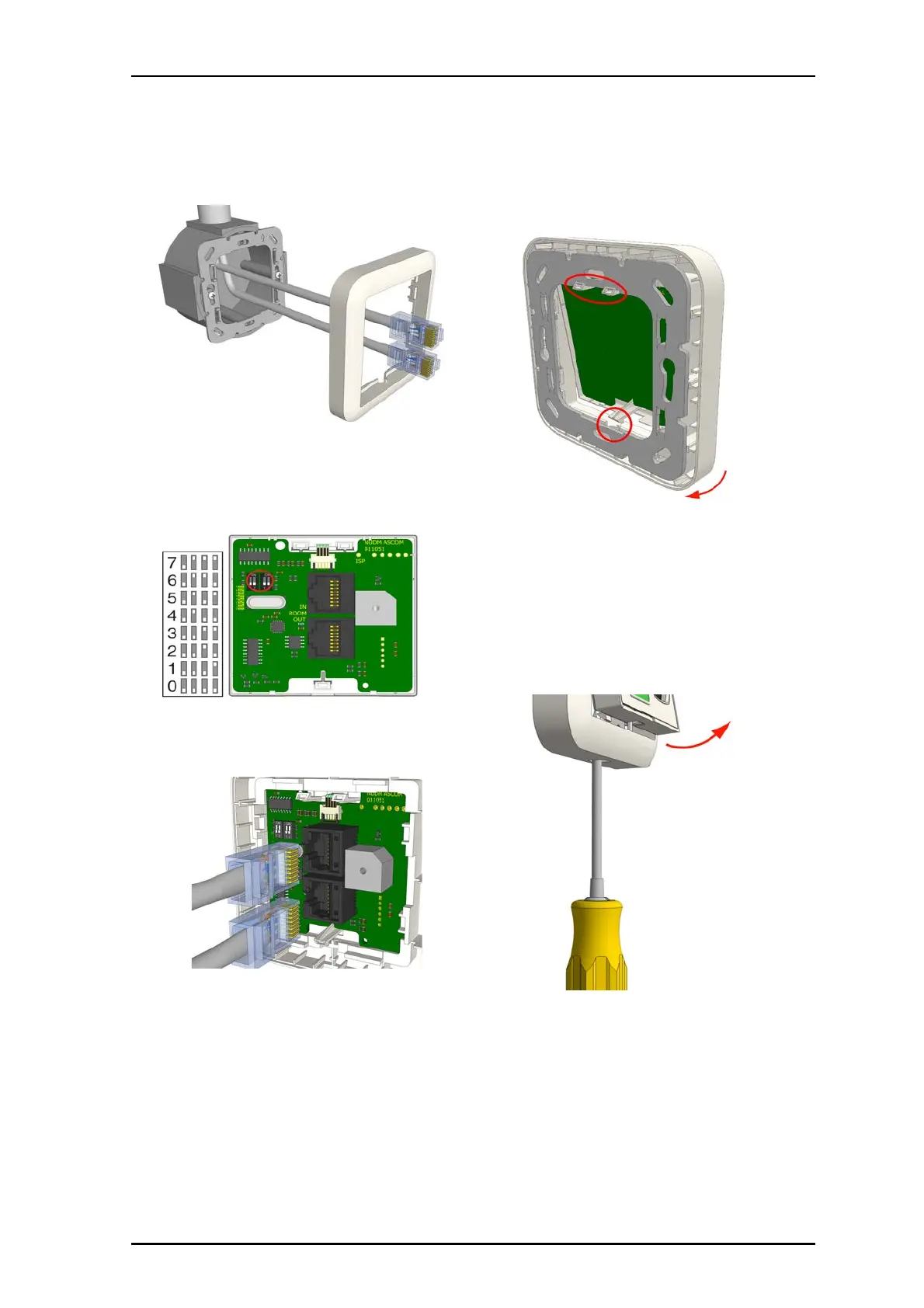
2. Set the DIP Switch to the correct room bus address (0...7).
3.
Insert the RJ-45 room bus connector into the first
jack, and then insert the next connector (to the next
module) into the other jack, as shown below. (IN from
the previous module and OUT to the next module).
To attach the module on the adapter:
1. Place the module against the frame, ensuring that
the module is facing up.
2. Place he module’s upper snap fasteners against
the upper edge of the adapter.
3. Press the module firmly against the adapter so
that the module’s bottom fasteners snap closed on
the adapter. See previous figure.
Removal
When separating the module from an adapter or spacer,
use a screwdriver with a blade that is approximately 6mm
wide.
To remove the module from a backbox or spacer:
1. Insert the #2 flat blade screwdriver into the slot at
the bottom of the module between the faceplate and
the adapter.
2.
Gently push the #2 flat blade screwdriver until the
module releases from the adapter.