25
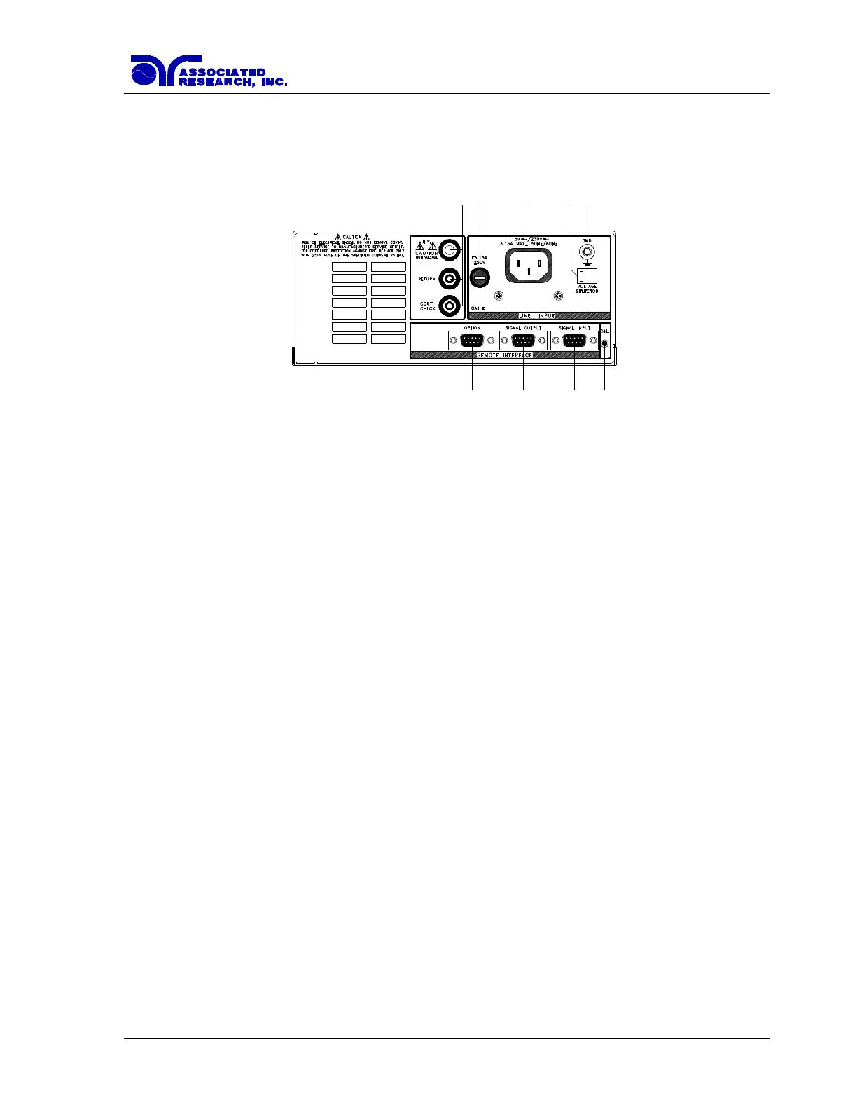
3.2.2. Rear Panel Controls
1. REAR PANEL OUTPUT CONNECTORS: These connectors are in parallel with the
front panel connectors.
2. FUSE RECEPTACLE: To change the fuse, unplug the power (mains) cord and turn the
fuse receptacle counter-clockwise. The fuse compartment will be exposed. Please replace
the fuse with one of the proper rating.
3. INPUT POWER RECEPTACLE: Standard IEC 320 connector for connection to a
standard NEMA style line power (mains) cord.
4. INPUT POWER SWITCH: Line voltage selection is set by the position of the switch. In
the left position it is set for 115 volt operation, in the right position it is set for 230 volt
operation.
5. CHASSIS GROUND (EARTH) TERMINAL: This terminal should be connected to a
good earth ground before operation.
6. OPTION CONNECTOR: Undefined.
7. REMOTE SIGNAL OUTPUT: 9-Pin D sub-miniature female connector for monitoring
PASS, FAIL, and PROCESSING output relay signals.
8. REMOTE SIGNAL INPUT: 9-Pin D subminiature male connector for remote control of
test, reset, and interlock functions, as well as remote program memory selection.
9. CALIBRATION BUTTON: To put the instrument into the calibration mode, push this
button and turn on the power switch simultaneously.
115
12
3
4
5
6 7 89
 Loading...