ASUS RS700A-E9 Series
4-17
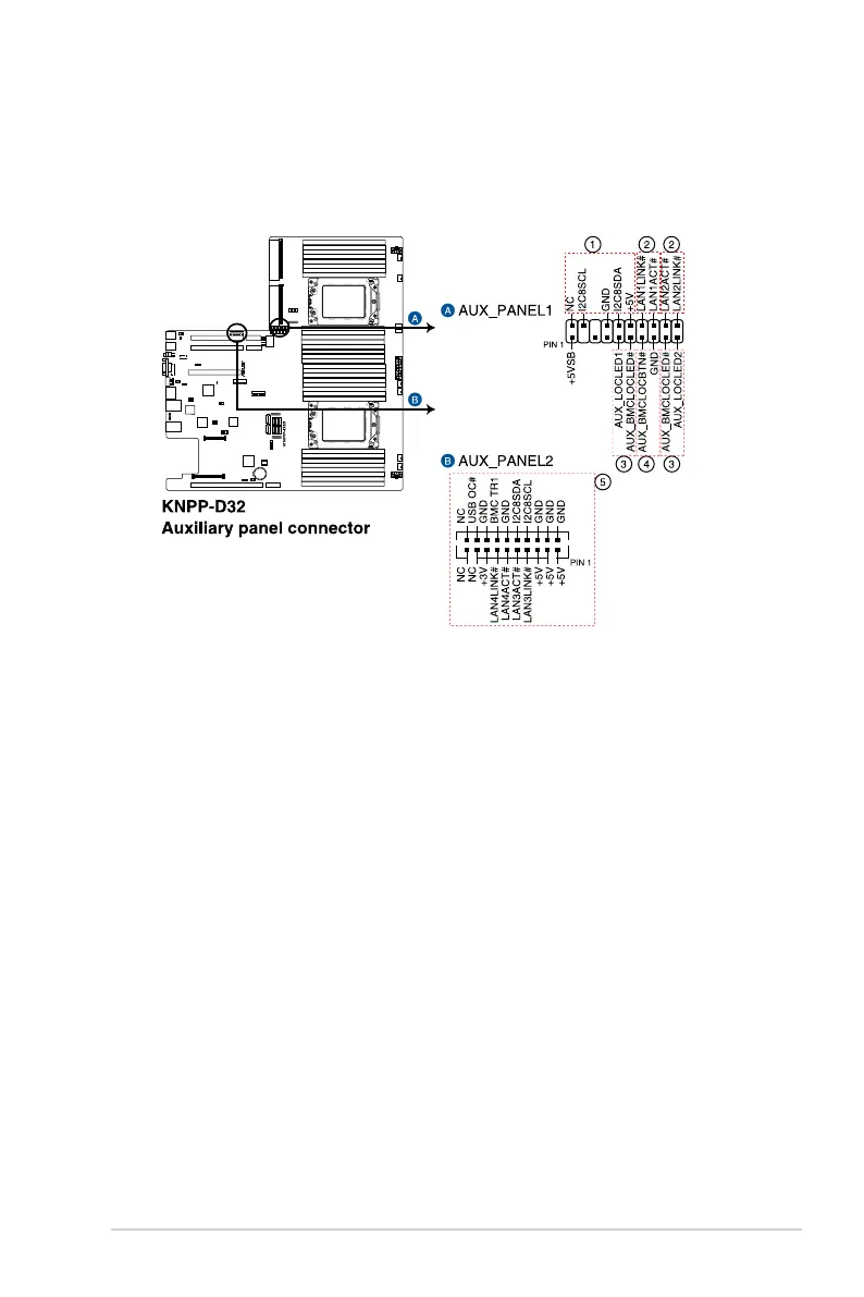
10. Auxiliary panel connector (20-2 pin AUX_PANEL1, 20-pin AUX_PANEL2)
This connector is for additional front panel features including front panel SMB, locator
LED and switch, chassis intrusion, and LAN LEDs.
1. Front panel SMB (6-1 pin FPSMB)
This 6-1 pin connector is for the front panel SMBus cable.
2. LAN activity LED (2-pin LAN1_LED, LAN2_LED)
This 2-pin connector is for the Gigabit LAN activity LEDs on the front panel.
3. Locator LED (2-pin LOCATORLED1, 2-pin LOCATORLED2)
This 2-pin connector is for the locator LED1 and LED2 on the front panel. Connect
the Locator LED cables to these 2-pin connector. The LEDs will light up when the
Locator button is pressed.
4. Locator Button/Switch (2-pin LOCATORBTN)
This 2-pin connector is for the locator button on the front panel. This button
queries the state of the system locator.
5. LAN activity LED and USB port (2-pin LAN3_LED, LAN4_LED, USB ports)
These 2-pin connectors are for the Gigabit LAN activity LEDs and USB ports on
the front panel.
 Loading...