Manual, Robotic Tool Changer, QC-5 through QC-27
Document #9610-20-2254-09
Pinnacle Park • 1041 Goodworth Drive • Apex, NC 27539 USA • Tel: 919.772.0115 • Fax: 919.772.8259 • www.ati-ia.com
28
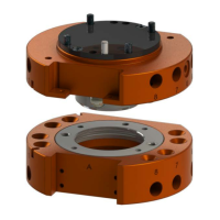
10. Insert a 3 mm hex key into the cam of the Tool Changer plate locking mechanism to
hold the piston.
11. Using a 2.5 mm hex key, tighten the M3 socket head cap screw to 12 in-lbs (1.36 Nm).
Figure 3.12—QC-11 Sensor Plate Assembly Installation
Tool Changer
Master Plate
3 mm Hex Key
2.5 mm Hex Key
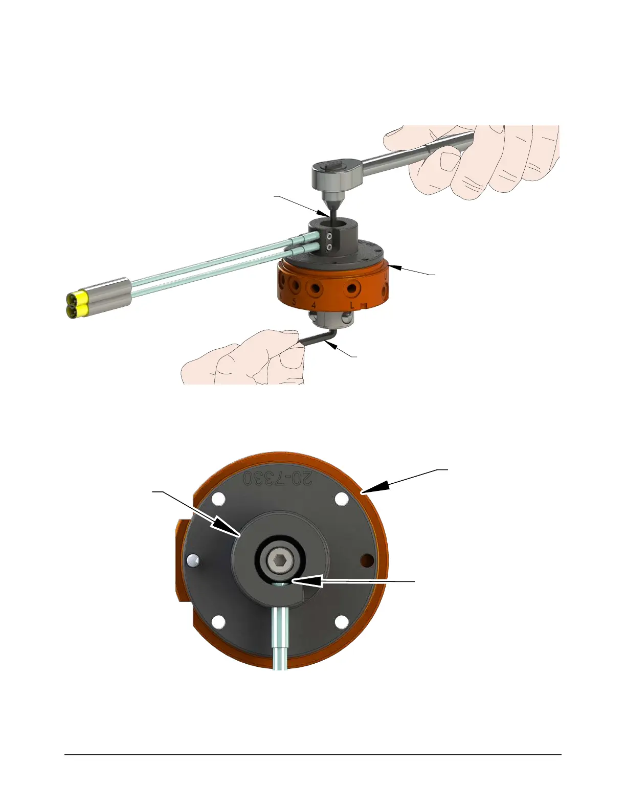
12. Look straight into the sensor plate assembly and verify the detection shaft does not touch the
Lock and Unlock sensors. If the sensors touch the shaft, adjust the sensor position. Refer to
Section 6.2.1—QC-11 and QC-27 Proximity Sensor Adjustment, Test, or Replacement.
Figure 3.13—Verify Sensor and Detection Shaft Clearance
Tool Changer
Master Plate
Clearance Between the
Lock/Unlock Sensors
and Detection Shaft
Sensor Plate
Assembly