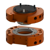
Manual, Robotic Tool Changer, QC-5 through QC-27
Document #9610-20-2254-09
Pinnacle Park • 1041 Goodworth Drive • Apex, NC 27539 USA • Tel: 919.772.0115 • Fax: 919.772.8259 • www.ati-ia.com
5
Glossary
Table 1.1—Tool Changer and Module Glossary
Term Denition
Bearing Race
A steel ring in the Tool plate that is engaged by the locking balls during the
coupling of the Tool Changer.
Cam
A multi tapered sliding cylinder attached to the piston that forces the locking balls
outward during the locking process.
Coupling The physical action of the locking the Master and Tool plates together. See Lock.
Cover Plate
A protective closure plate on the standard Master assemblies which closes the
pneumatic chamber.
Detection Shaft
A threaded stem inserted into the robot side of the piston and functions as a
target to actuate the Lock/Unlock sensors.
Electrical Module
Utility modules that pass electrical power and signals through the Master and
Tool modules to the end-effector.
End-Effector Tool used by the robot to perform a particular operation or function.
Fluid Module
Utility modules that pass uids through the Master and Tool modules to the end-
effector.
High Current Module
Utility modules that pass electrical power through the Master and Tool modules to
the end-effector.
Interface Plate (IP)
An optional customized component that is used to adapt a Tool Changer to the
user’s robot or tooling.
Lock
The lock air pressure that is provided to the Master plate locking mechanism to
force the cam to press the locking balls against the bearing race and lock the
Master and Tool plates together.
Lock Port
A pneumatic port on the Master plate through which air pressure is supplied to
Lock the Master plate to the Tool plate.
Lock Sensor
A proximity sensor that detects the position of the pneumatically actuated piston
when it is in the locked or missed tool position.
Locked
An output signal provided by a proximity sensor that indicates the coupling
mechanism is in the Locked position.
Locking Balls
Hardened steel ball bearings used in the fail-safe locking mechanism. The
locking balls are forced outward by the cam against the bearing race to pull the
Master and Tool plates together.
Locking Mechanism
A manual, pneumatic or electrical driven device that draws the Master and
Tool plates together and secures them in a fail-safe locked condition until the
mechanism is unlocked. The locking mechanism consists of locking balls, cam,
ball cage, bearing race, and either an lever, pneumatic cylinder, or an electric
motor.
L/U
Lock/Unlock sensing capability that allows the customer to determine the state of
the Master assembly locking mechanism.
Master plate
The half of the Tool Changer that is mounted to a robot. The Master plate
contains the locking mechanism.
Moment The applied force multiplied by the distance it is from a point.
No-Touch™
A design feature of all ATI Tool Changer products that allows the Master plate
and Tool plate to couple without physical contact prior to locking.
Piston A cylinder located in the Master plate that actuates the locking mechanism.

 Loading...