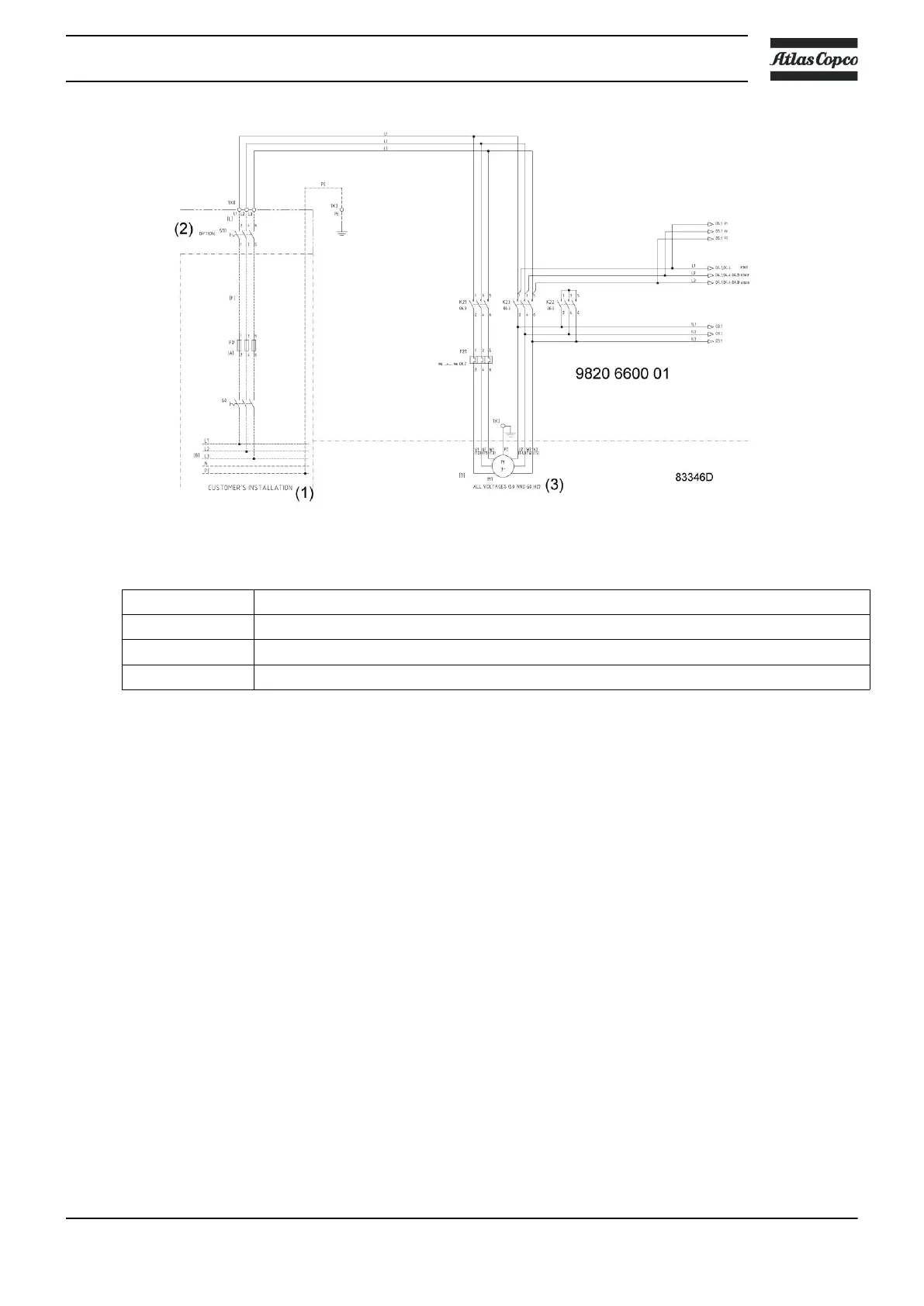
Electrical connections for GA 30
+
up to GA 45
+
Reference Designation
(1) Customer’s installation
(2) Option
(3) All voltages (50 and 60 Hz)
Instructions
1. Provide an isolating switch.
2. Check that the motor cables and wires inside the electric cabinet are clamped tight to their
terminals.
3. Check the fuses and the setting of the overload relay. See section Electrical cable size.
4. Connect the power supply cables to their terminals L1, L2, L3.
5. Connect earth conductor bolt (PE).
Compressor status indication
On compressors equipped with an Elektronikon™ Swipe controller, the controller is provided with
an auxiliary relay (K05) for remote indication of a shutdown. This NO contact (NO = normally
open) will be closed if all conditions are normal and will open in case of power failure or
shutdown.
Maximum contact load: 10 A / 250 V AC.
On compressors equipped with an Elektronikon™ Touch controller, the controller is provided with
potential free auxiliary NO contacts (NO = normally open) (K05, K07 and K08) for remote
indication of:
• Manual load/unload or automatic operation (K07)
• Warning condition (K08)
Instruction book
2920 7109 51 119
 Loading...