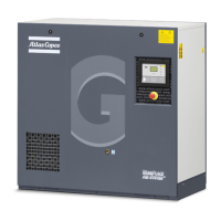
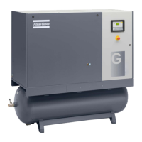
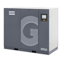
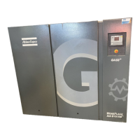
Compressor type I (1) Max. fuse (1) I (2) Max. fuse (2)
gL/gG gL/gG
V Hz A A A A
GA 45
+
200 50 203 224 215 250
GA 45
+
400 50 102 125 106 125
GA 45
+
200 60 223 250 234 315
GA 45
+
230 60 194 224 205 224
GA 45
+
380 60 118 160 123 160
GA 45
+
460 60 98 125 102 125
I: current in the supply lines at maximum load and nominal voltage
(1): compressors without integrated dryer
(2): compressors with integrated dryer
Fuse calculations for IEC are done according to 60364-4-43 Low-voltage electrical installations
- Part 4-43: protection against overcurrent. Fuse sizes are calculated in order to protect the cable
against short circuit.
Possible configurations
There are 3 possible cabling layouts:
• (1): Single supply cables.
• (2): Parallel supply cables
• (3) is only valid for Y-D versions
Cable sizing according IEC
The tables below indicate the current carrying capacities of cables for commonly used installation
methods, calculated according to standard 60364-5-52 - electrical installations of buildings part 5
- selection and erection equipment and section 52 - current carrying capacities in wiring systems.
The allowed currents are valid for PVC insulated cables with three loaded copper conductors.
See tables for maximum conductor temperature 70 °C and for maximum conductor temperature
90°C.
Instruction book
162 2920 7109 51

 Loading...

