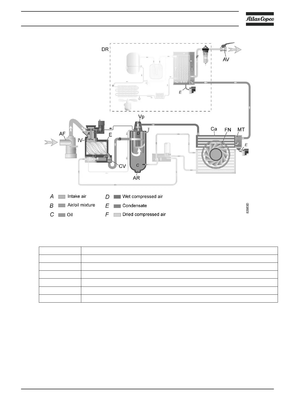
Flow diagram, GA Workplace Full-Feature
Reference Description
A Intake air
B Air/oil mixture
C Oil
D Wet compressed air
E Condensate
F Dried compressed air
Note: The cooling fan is not provided on water-cooled compressors.
Description
Air drawn through filter (AF) and open inlet valve (IV) of unloader is compressed in compressor
element (E). A mixture of compressed air and oil flows into the air receiver/oil separator (AR) via
check valve (CV). The air is discharged through outlet valve (AV) via minimum pressure valve
(Vp) and air cooler (Ca).
The air cooler is provided with a moisture trap (MT).
Instruction book
2920 7109 51 17
 Loading...