4.2.2. JTAG Physical Interface
The JTAG interface consists of a 4-wire Test Access Port (TAP) controller that is compliant with the IEEE
®
1149.1 standard. The IEEE standard was developed to provide an industry-standard way to efficiently test
circuit board connectivity (Boundary Scan). Atmel AVR and SAM devices have extended this functionality
to include full Programming and On-chip Debugging support.
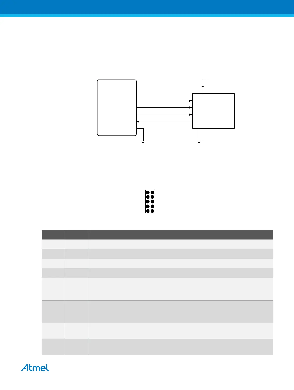
Figure 4-1. JTAG Interface Basics
Vcc
TMS
TDI
TDO
TCK
programmer /
debugger
Atmel
target
device
4.2.2.1. SAM JTAG Pinout (Cortex-M debug connector)
When designing an application PCB which includes an Atmel SAM with the JTAG interface, it is
recommended to use the pinout as shown in the figure below. Both 100-mil and 50-mil variants of this
pinout are supported, depending on the cabling and adapters included with the particular kit.
Figure 4-2. SAM JTAG Header Pinout
TMS
TCK
TDO
TDI
nRESET
VCC
GND
GND
(KEY)
GND
1 2
SAM JTAG
Table 4-1. SAM JTAG Pin Description
Name Pin Description
TCK 4 Test Clock (clock signal from the Atmel-ICE into the target device).
TMS 2 Test Mode Select (control signal from the Atmel-ICE into the target device).
TDI 8 Test Data In (data transmitted from the Atmel-ICE into the target device).
TDO 6 Test Data Out (data transmitted from the target device into the Atmel-ICE).
nRESET 10 Reset (optional). Used to reset the target device. Connecting this pin is
recommended since it allows the Atmel-ICE to hold the target device in a reset
state, which can be essential to debugging in certain scenarios.
VTG 1 Target voltage reference. The Atmel-ICE samples the target voltage on this pin in
order to power the level converters correctly. The Atmel-ICE draws less than 1mA
from this pin in this mode.
GND 3, 5, 9 Ground. All must be connected to ensure that the Atmel-ICE and the target device
share the same ground reference.
KEY 7 Connected internally to the TRST pin on the AVR connector. Recommended as not
connected.
Atmel Atmel-ICE [USER GUIDE]
Atmel-42330C-Atmel-ICE_User Guide-10/2016
25

 Loading...


