Table 4-3. Atmel-ICE JTAG Pin Description
Name AVR
port
pin
SAM
port
pin
Description
TCK 1 4 Test Clock (clock signal from the Atmel-ICE into the target device).
TMS 5 2 Test Mode Select (control signal from the Atmel-ICE into the target device).
TDI 9 8 Test Data In (data transmitted from the Atmel-ICE into the target device).
TDO 3 6 Test Data Out (data transmitted from the target device into the Atmel-ICE).
nTRST 8 - Test Reset (optional, only on some AVR devices). Used to reset the JTAG
TAP controller.
nSRST 6 10 Reset (optional). Used to reset the target device. Connecting this pin is
recommended since it allows the Atmel-ICE to hold the target device in a
reset state, which can be essential to debugging in certain scenarios.
VTG 4 1 Target voltage reference. The Atmel-ICE samples the target voltage on this
pin in order to power the level converters correctly. The Atmel-ICE draws
less than 3mA from this pin in debugWIRE mode and less than 1mA in
other modes.
GND 2, 10 3, 5, 9 Ground. All must be connected to ensure that the Atmel-ICE and the target
device share the same ground reference.
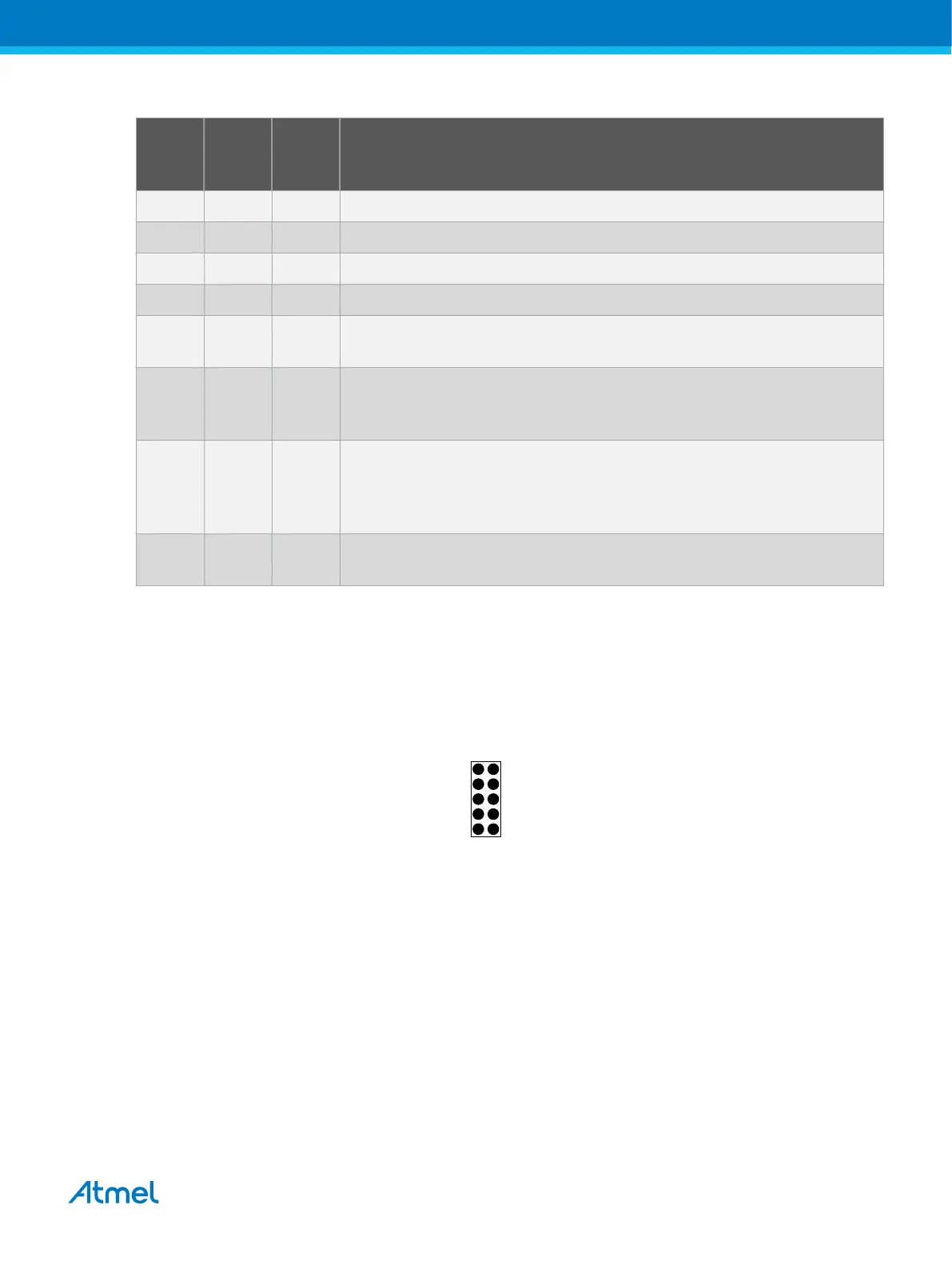
4.2.4. SWD Physical Interface
The ARM SWD interface is a subset of the JTAG interface, making use of TCK and TMS pins. The ARM
JTAG and AVR JTAG connectors are, however, not pin-compatible, so when designing an application
PCB, which uses a SAM device with SWD or JTAG interface, it is recommended to use the ARM pinout
shown in the figure below. The SAM connector port on the Atmel-ICE can connect directly to this pinout.
Figure 4-4. Recommended ARM SWD/JTAG Header Pinout
SWDIO
SWDCLK
SWO
nRESET
VCC
GND
GND
(KEY)
GND
1 2
SAM SWD
(NC)
The Atmel-ICE is capable of streaming UART-format ITM trace to the host computer. Trace is captured on
the TRACE/SWO pin of the 10-pin header (JTAG TDO pin). Data is buffered internally on the Atmel-ICE
and is sent over the HID interface to the host computer. The maximum reliable data rate is about 3MB/s.
4.2.5. Connecting to an SWD Target
The ARM SWD interface is a subset of the JTAG interface, making use of the TCK and TMS pins, which
means that when connecting to an SWD device, the 10-pin JTAG connector can technically be used. The
ARM JTAG and AVR JTAG connectors are, however, not pin-compatible, so this depends upon the layout
of the target board in use. When using an STK600 or a board making use of the AVR JTAG pinout, the
AVR connector port on the Atmel-ICE must be used. When connecting to a board, which makes use of
the ARM JTAG pinout, the SAM connector port on the Atmel-ICE must be used.
The recommended pinout for the 10-pin Cortex Debug connector is shown in Figure 4-4.
Connection to a 10-pin 50-mil Cortex header
Atmel Atmel-ICE [USER GUIDE]
Atmel-42330C-Atmel-ICE_User Guide-10/2016
28

 Loading...


