When the UPDI interface is on a shared pin, the pin can be configured to be either UPDI, /RESET, or
GPIO by setting the RSTPINCFG[1:0] fuses.
The RSTPINCFG[1:0] fuses have the following configurations, as described in the datasheet. The
practical implications of each choice are given here.
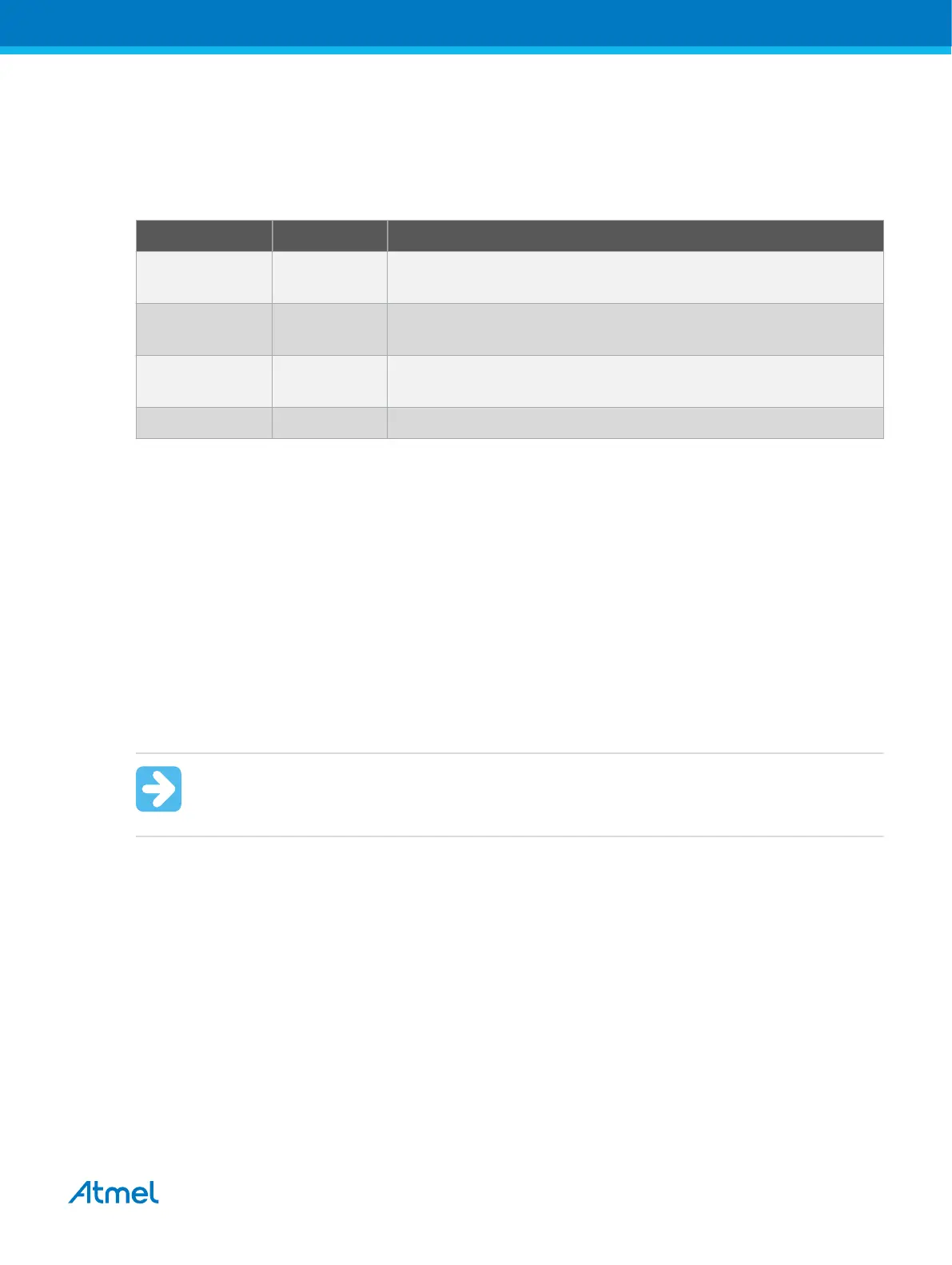
Table 4-13. RSTPINCFG[1:0] Fuse Configuration
RSTPINCFG[1:0] Configuration Usage
00 GPIO General purpose I/O pin. In order to access UPDI, a 12V pulse must
be applied to this pin. No external reset source is available.
01 UPDI Dedicated programming and debugging pin. No external reset
source is available.
10 Reset Reset signal input. In order to access UPDI, a 12V pulse must be
applied to this pin.
11 Reserved NA
Note: Older AVR devices have a programming interface, known as "High-Voltage Programming" (both
serial and parallel variants exist.) In general this interface requires 12V to be applied to the /RESET pin
for the duration of the programming session. The UPDI interface is an entirely different interface. The
UPDI pin is primarily a programming and debugging pin, which can be fused to have an alternative
function (/RESET or GPIO). If the alternative function is selected then a 12V pulse is required on that pin
in order to re-activate the UPDI functionality.
Note: If a design requires the sharing of the UPDI signal due to pin constraints, steps must be taken in
order to ensure that the device can be programmed. To ensure that the UPDI signal can function
correctly, as well as to avoid damage to external components from the 12V pulse, it is recommended to
disconnect any components on this pin when attempting to debug or program the device. This can be
done using a 0Ω resistor, which is mounted by default and removed or replaced by a pin header while
debugging. This configuration effectively means that programming should be done before mounting the
device.
Important: The Atmel-ICE does not support 12V on the UPDI line. In other words, if the UPDI
pin has been configured as GPIO or RESET the Atmel-ICE will not be able to enable the UPDI
interface.
4.4.8. Connecting to a UPDI Target
The recommended pinout for the 6-pin UPDI connector is shown in Figure 4-12.
Connection to a 6-pin 100-mil UPDI header
Use the 6-pin 100-mil tap on the flat cable (included in some kits) to connect to a standard 100-mil UPDI
header.
Connection to a 6-pin 50-mil UPDI header
Use the adapter board (included in some kits) to connect to a standard 50-mil UPDI header.
Connection to a custom 100-mil header
The 10-pin mini-squid cable should be used to connect between the Atmel-ICE AVR connector port and
the target board. Three connections are required, as described in the table below.
Atmel Atmel-ICE [USER GUIDE]
Atmel-42330C-Atmel-ICE_User Guide-10/2016
41
 Loading...


