Use a standard 50-mil to 100-mil adapter to connect to 100-mil headers. An adapter board (included in
some kits) can be used for this purpose, or alternatively the JTAGICE3 adapter can be used for AVR
targets.
Important:
The JTAGICE3 100-mil adapter cannot be used with the SAM connector port, since pins 2 and
10 (AVR GND) on the adapter are connected.
Connection to a custom 100-mil header
If your target board does not have a compliant 10-pin JTAG header in 50- or 100-mil, you can map to a
custom pinout using the 10-pin "mini-squid" cable (included in some kits), which gives access to ten
individual 100-mil sockets.
Connection to a 20-pin 100-mil header
Use the adapter board (included in some kits) to connect to targets with a 20-pin 100-mil header.
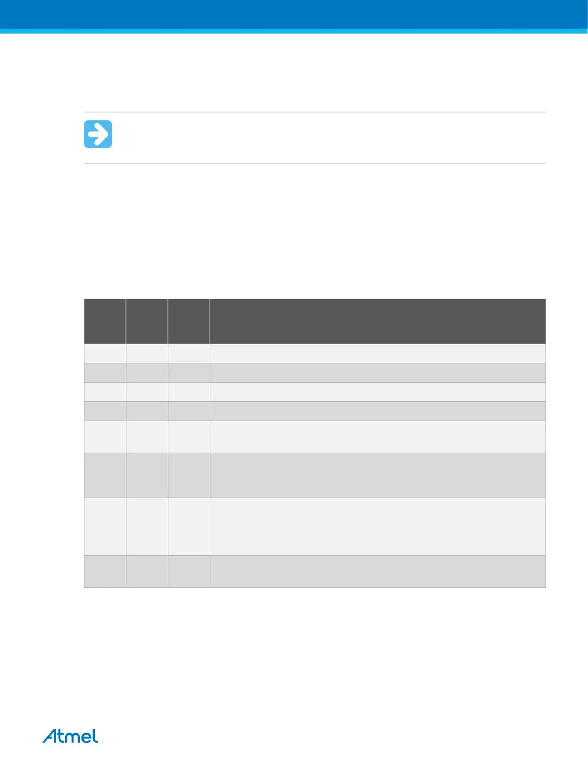
Table 4-7. Atmel-ICE JTAG Pin Description
Name AVR
port
pin
SAM
port
pin
Description
TCK 1 4 Test Clock (clock signal from the Atmel-ICE into the target device).
TMS 5 2 Test Mode Select (control signal from the Atmel-ICE into the target device).
TDI 9 8 Test Data In (data transmitted from the Atmel-ICE into the target device).
TDO 3 6 Test Data Out (data transmitted from the target device into the Atmel-ICE).
nTRST 8 - Test Reset (optional, only on some AVR devices). Used to reset the JTAG
TAP controller.
nSRST 6 10 Reset (optional). Used to reset the target device. Connecting this pin is
recommended since it allows the Atmel-ICE to hold the target device in a
reset state, which can be essential to debugging in certain scenarios.
VTG 4 1 Target voltage reference. The Atmel-ICE samples the target voltage on this
pin in order to power the level converters correctly. The Atmel-ICE draws
less than 3mA from this pin in debugWIRE mode and less than 1mA in
other modes.
GND 2, 10 3, 5, 9 Ground. All must be connected to ensure that the Atmel-ICE and the target
device share the same ground reference.
4.3.4. aWire Physical Interface
The aWire interface makes use of the RESET wire of the AVR device to allow programming and
debugging functions. A special enable sequence is transmitted by the Atmel-ICE, which disables the
default RESET functionality of the pin.
When designing an application PCB, which includes an Atmel AVR with the aWire interface, it is
recommended to use the pinout as shown in Figure 4-8. Both 100-mil and 50-mil variants of this pinout
are supported, depending on the cabling and adapters included with the particular kit.
Atmel Atmel-ICE [USER GUIDE]
Atmel-42330C-Atmel-ICE_User Guide-10/2016
33

 Loading...


