3. Connecting the Atmel-ICE
3.1. Connecting to AVR and SAM Target Devices
The Atmel-ICE is equipped with two 50-mil 10-pin JTAG connectors. Both connectors are directly
electrically connected, but conform to two different pinouts; the AVR JTAG header and the ARM Cortex
Debug header. The connector should be selected based on the pinout of the target board, and not the
target MCU type - for example a SAM device mounted in an AVR STK
®
600 stack should use the AVR
header.
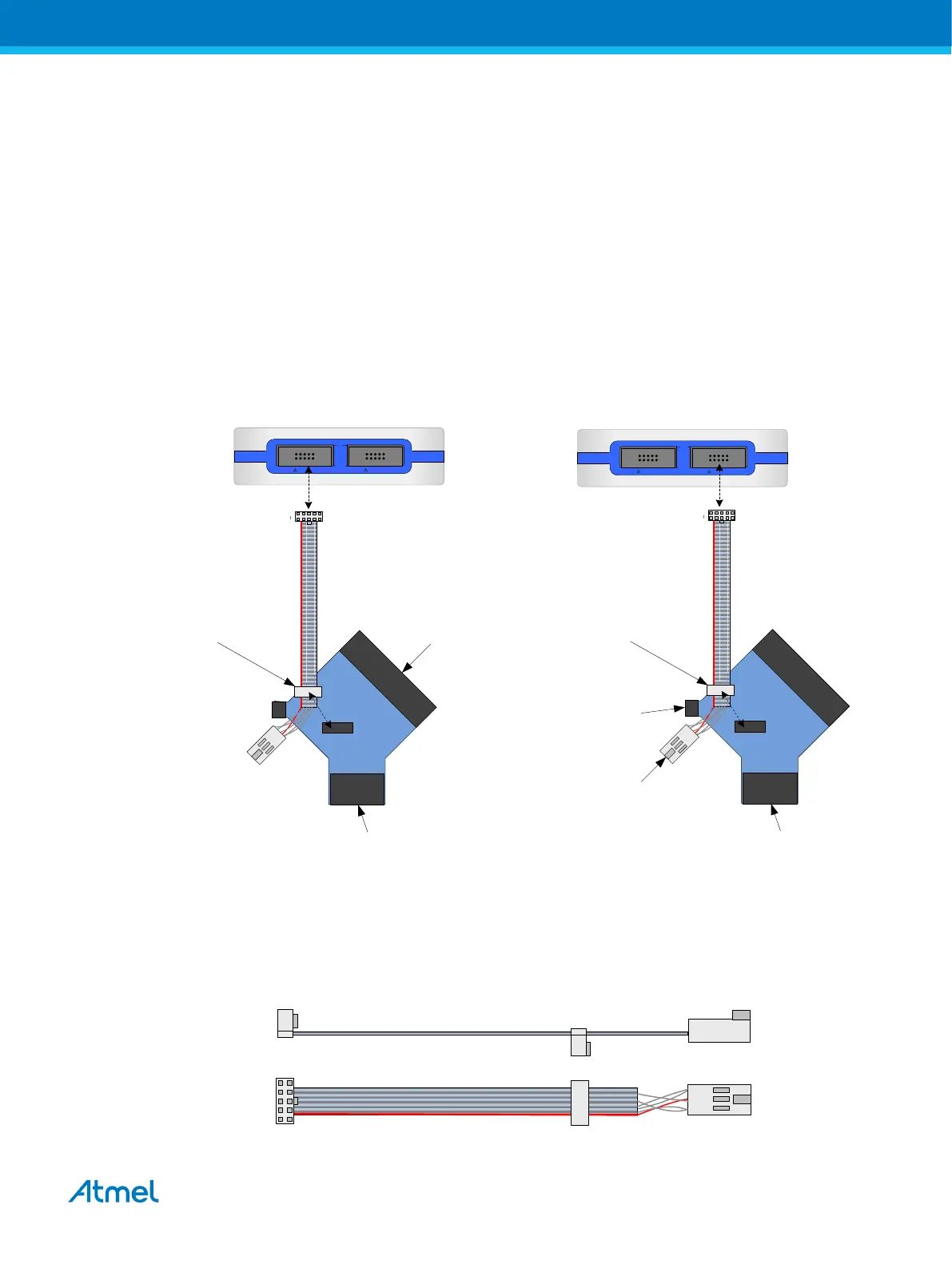
Various cabling and adapters are available in the different Atmel-ICE kits. An overview of connection
options is shown.
Figure 3-1. Atmel-ICE Connection Options
6-pin 100-mil AVR ISP/
debugWIRE/PDI/aWire/
TPI header
10-pin 100-mil AVR
JTAG header
10-pin 50-mil AVR
JTAG header
SAM AVR
20-pin 100-mil SAM
header
(for EVKs etc)
10-pin 100-mil
JTAG/SWD header
10-pin 50-mil JTAG/SWD
(Cortex debug header)
SAM AVR
6-pin 50-mil AVR ISP/
debugWIRE/PDI/aWire/
TPI header
The red wire marks pin 1 of the 10-pin 50-mil connector. Pin 1 of the 6-pin 100-mil connector is placed to
the right of the keying when the connector is seen from the cable. Pin 1 of each connector on the adapter
is marked with a white dot. The figure below shows the pinout of the debug cable. The connector marked
A plugs into the debugger while the B side plugs into the target board.
Figure 3-2. Debug Cable Pinout
A B
1 2
9
1 2
9 10
1
1
2
5
10
Atmel Atmel-ICE [USER GUIDE]
Atmel-42330C-Atmel-ICE_User Guide-10/2016
15

 Loading...


