Use the flat cable (included in some kits) to connect to a standard 50-mil Cortex header.
Connection to a 10-pin 100-mil Cortex-layout header
Use the adapter board (included in some kits) to connect to a 100-mil Cortex-pinout header.
Connection to a 20-pin 100-mil SAM header
Use the adapter board (included in some kits) to connect to a 20-pin 100-mil SAM header.
Connection to a custom 100-mil header
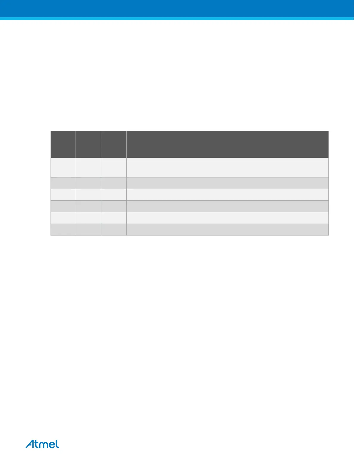
The 10-pin mini-squid cable should be used to connect between the Atmel-ICE AVR or SAM connector
port and the target board. Six connections are required, as described in the table below.
Table 4-4. Atmel-ICE SWD Pin Mapping
Name AVR
port
pin
SAM
port
pin
Description
SWDC
LK
1 4 Serial Wire Debug Clock.
SWDIO 5 2 Serial Wire Debug Data Input/Output.
SWO 3 6 Serial Wire Output (optional- not implemented on all devices).
nSRST 6 10 Reset.
VTG 4 1 Target voltage reference.
GND 2, 10 3, 5, 9 Ground.
4.2.6. Special Considerations
ERASE pin
Some SAM devices include an ERASE pin which is asserted to perform a complete chip erase and
unlock devices on which the security bit is set. This feature is coupled to the device itself as well as the
flash controller and is not part of the ARM core.
The ERASE pin is NOT part of any debug header, and the Atmel-ICE is thus unable to assert this signal
to unlock a device. In such cases the user should perform the erase manually before starting a debug
session.
Physical interfaces
JTAG interface
The RESET line should always be connected so that the Atmel-ICE can enable the JTAG interface.
SWD interface
The RESET line should always be connected so that the Atmel-ICE can enable the SWD interface.
4.3. AVR UC3 Devices with JTAG/aWire
All AVR UC3 devices feature the JTAG interface for programming and debugging. In addition, some AVR
UC3 devices feature the aWire interface with identical functionality using a single wire. Check the device
datasheet for supported interfaces of that device.
Atmel Atmel-ICE [USER GUIDE]
Atmel-42330C-Atmel-ICE_User Guide-10/2016
29

 Loading...


