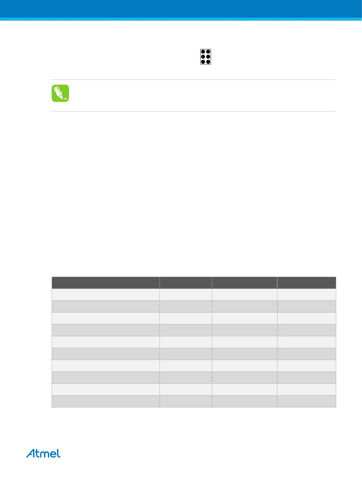
Figure 4-8. aWire Header Pinout
(RESET_N) DATA VCC
GND
1 2
aWire
(NC)
(NC)
(NC)
Tip:
Since aWire is a half-duplex interface, a pull-up resistor on the RESET line in the order of 47kΩ
is recommended to avoid false start-bit detection when changing direction.
The aWire interface can be used as both a programming and debugging interface. All features of the
OCD system available through the 10-pin JTAG interface can also be accessed using aWire.
4.3.5. Connecting to an aWire Target
The aWire interface requires only one data line in addition to V
CC
and GND. On the target this line is the
nRESET line, although the debugger uses the JTAG TDO line as the data line.
The recommended pinout for the 6-pin aWire connector is shown in Figure 4-8.
Connection to a 6-pin 100-mil aWire header
Use the 6-pin 100-mil tap on the flat cable (included in some kits) to connect to a standard 100-mil aWire
header.
Connection to a 6-pin 50-mil aWire header
Use the adapter board (included in some kits) to connect to a standard 50-mil aWire header.
Connection to a custom 100-mil header
The 10-pin mini-squid cable should be used to connect between the Atmel-ICE AVR connector port and
the target board. Three connections are required, as described in the table below.
Table 4-8. Atmel-ICE aWire Pin Mapping
Atmel-ICE AVR port pins Target pins Mini-squid pin aWire pinout
Pin 1 (TCK) 1
Pin 2 (GND) GND 2 6
Pin 3 (TDO) DATA 3 1
Pin 4 (VTG) VTG 4 2
Pin 5 (TMS) 5
Pin 6 (nSRST) 6
Pin 7 (Not connected) 7
Pin 8 (nTRST) 8
Pin 9 (TDI) 9
Pin 10 (GND) 0
Atmel Atmel-ICE [USER GUIDE]
Atmel-42330C-Atmel-ICE_User Guide-10/2016
34

 Loading...


