Info:
The SPI interface is often referred to as "ISP", since it was the first In System Programming
interface on Atmel AVR products. Other interfaces are now available for In System
Programming.
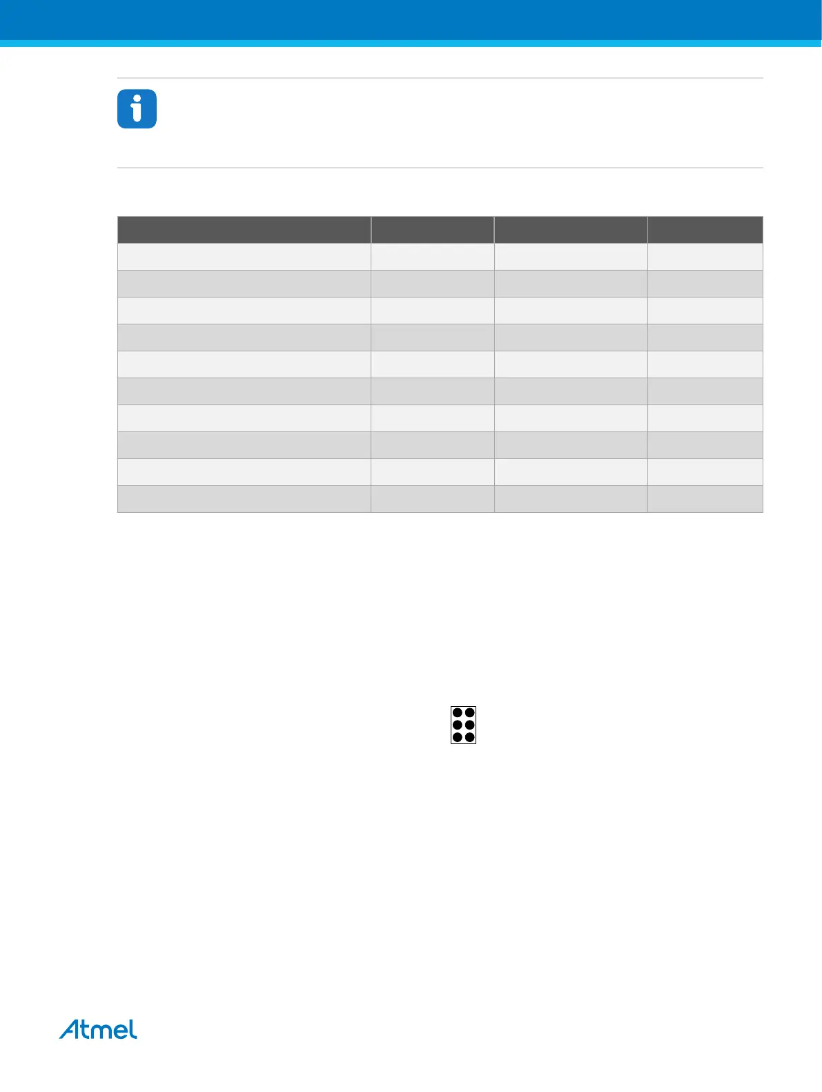
Table 4-11. Atmel-ICE SPI Pin Mapping
Atmel-ICE AVR port pins Target pins Mini-squid pin SPI pinout
Pin 1 (TCK) SCK 1 3
Pin 2 (GND) GND 2 6
Pin 3 (TDO) MISO 3 1
Pin 4 (VTG) VTG 4 2
Pin 5 (TMS) 5
Pin 6 (nSRST) /RESET 6 5
Pin 7 (not connected) 7
Pin 8 (nTRST) 8
Pin 9 (TDI) MOSI 9 4
Pin 10 (GND) 0
4.4.5. PDI
The Program and Debug Interface (PDI) is an Atmel proprietary interface for external programming and
on-chip debugging of a device. PDI Physical is a 2-pin interface providing a bi-directional half-duplex
synchronous communication with the target device.
When designing an application PCB, which includes an Atmel AVR with the PDI interface, the pinout
shown in the figure below should be used. One of the 6-pin adapters provided with the Atmel-ICE kit can
then be used to connect the Atmel-ICE probe to the application PCB.
Figure 4-11. PDI Header Pinout
PDI_DATA
PDI_CLK
VCC
GND
1 2
PDI
(NC)
(NC)
4.4.6. Connecting to a PDI Target
The recommended pinout for the 6-pin PDI connector is shown in Figure 4-11.
Connection to a 6-pin 100-mil PDI header
Use the 6-pin 100-mil tap on the flat cable (included in some kits) to connect to a standard 100-mil PDI
header.
Connection to a 6-pin 50-mil PDI header
Use the adapter board (included in some kits) to connect to a standard 50-mil PDI header.
Connection to a custom 100-mil header
Atmel Atmel-ICE [USER GUIDE]
Atmel-42330C-Atmel-ICE_User Guide-10/2016
39

 Loading...


