The 10-pin mini-squid cable should be used to connect between the Atmel-ICE AVR connector port and
the target board. Four connections are required, as described in the table below.
Important:
The pinout required is different from the JTAGICE mkII JTAG probe, where PDI_DATA is
connected to pin 9. The Atmel-ICE is compatible with the pinout used by the Atmel-ICE,
JTAGICE3, AVR ONE!, and AVR Dragon
™
products.
Table 4-12. Atmel-ICE PDI Pin Mapping
Atmel-ICE AVR port pin Target pins Mini-squid pin Atmel STK600 PDI pinout
Pin 1 (TCK) 1
Pin 2 (GND) GND 2 6
Pin 3 (TDO) PDI_DATA 3 1
Pin 4 (VTG) VTG 4 2
Pin 5 (TMS) 5
Pin 6 (nSRST) PDI_CLK 6 5
Pin 7 (not connected) 7
Pin 8 (nTRST) 8
Pin 9 (TDI) 9
Pin 10 (GND) 0
4.4.7. UPDI Physical Interface
The Unified Program and Debug Interface (UPDI) is an Atmel proprietary interface for external
programming and on-chip debugging of a device. It is a successor to the PDI 2-wire physical interface,
which is found on all AVR XMEGA devices. UPDI is a single-wire interface providing a bi-directional half-
duplex asynchronous communication with the target device for purposes of programming and debugging.
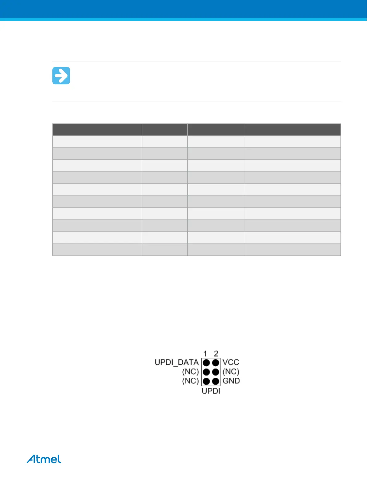
When designing an application PCB, which includes an Atmel AVR with the UPDI interface, the pinout
shown below should be used. One of the 6-pin adapters provided with the Atmel-ICE kit can then be used
to connect the Atmel-ICE probe to the application PCB.
Figure 4-12. UPDI Header Pinout
4.4.7.1. UPDI and /RESET
The UPDI one-wire interface can be a dedicated pin or a shared pin, depending on the target AVR device.
Consult the device datasheet for further information.
Atmel Atmel-ICE [USER GUIDE]
Atmel-42330C-Atmel-ICE_User Guide-10/2016
40

 Loading...


