3.2. Connecting to a JTAG Target
The Atmel-ICE is equipped with two 50-mil 10-pin JTAG connectors. Both connectors are directly
electrically connected, but conform to two different pinouts; the AVR JTAG header and the ARM Cortex
Debug header. The connector should be selected based on the pinout of the target board, and not the
target MCU type - for example a SAM device mounted in an AVR STK600 stack should use the AVR
header.
The recommended pinout for the 10-pin AVR JTAG connector is shown in Figure 4-6.
The recommended pinout for the 10-pin ARM Cortex Debug connector is shown in Figure 4-2.
Direct connection to a standard 10-pin 50-mil header
Use the 50-mil 10-pin flat cable (included in some kits) to connect directly to a board supporting this
header type. Use the AVR connector port on the Atmel-ICE for headers with the AVR pinout, and the SAM
connector port for headers complying with the ARM Cortex Debug header pinout.
The pinouts for both 10-pin connector ports are shown below.
Connection to a standard 10-pin 100-mil header
Use a standard 50-mil to 100-mil adapter to connect to 100-mil headers. An adapter board (included in
some kits) can be used for this purpose, or alternatively the JTAGICE3 adapter can be used for AVR
targets.
Important:
The JTAGICE3 100-mil adapter cannot be used with the SAM connector port, since pins 2 and
10 (AVR GND) on the adapter are connected.
Connection to a custom 100-mil header
If your target board does not have a compliant 10-pin JTAG header in 50- or 100-mil, you can map to a
custom pinout using the 10-pin "mini-squid" cable (included in some kits), which gives access to ten
individual 100-mil sockets.
Connection to a 20-pin 100-mil header
Use the adapter board (included in some kits) to connect to targets with a 20-pin 100-mil header.
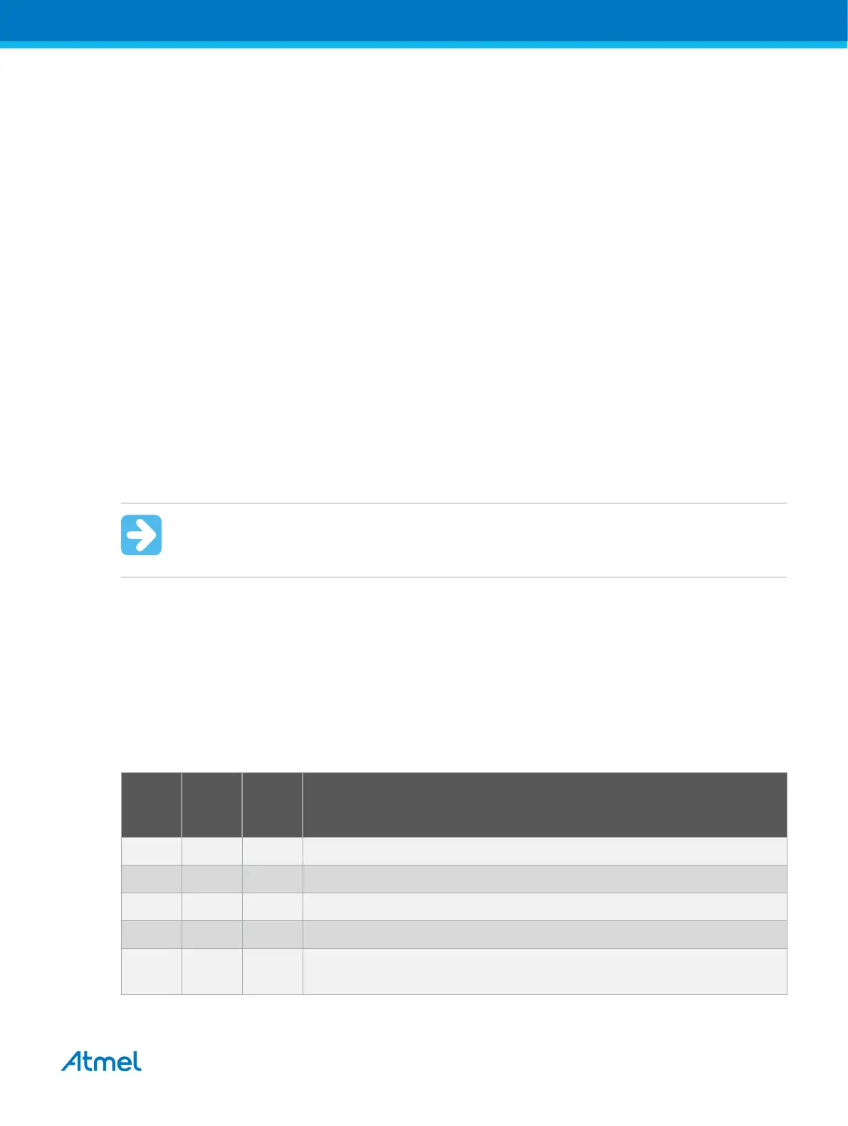
Table 3-1. Atmel-ICE JTAG Pin Description
Name AVR
port
pin
SAM
port
pin
Description
TCK 1 4 Test Clock (clock signal from the Atmel-ICE into the target device).
TMS 5 2 Test Mode Select (control signal from the Atmel-ICE into the target device).
TDI 9 8 Test Data In (data transmitted from the Atmel-ICE into the target device).
TDO 3 6 Test Data Out (data transmitted from the target device into the Atmel-ICE).
nTRST 8 - Test Reset (optional, only on some AVR devices). Used to reset the JTAG
TAP controller.
Atmel Atmel-ICE [USER GUIDE]
Atmel-42330C-Atmel-ICE_User Guide-10/2016
16

 Loading...


