5. Hardware Description
5.1. LEDs
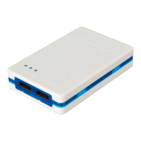
The Atmel-ICE top panel has three LEDs which indicate the status of current debug or programming
sessions.
Table 5-1. LEDs
LED Function Description
Left Target power GREEN when target power is OK. Flashing indicates a target power
error. Does not light up until a programming/debugging session
connection is started.
Middle Main power RED when main-board power is OK.
Right Status Flashing GREEN when the target is running/stepping. OFF when
target is stopped.
5.2. Rear Panel
The rear panel of the Atmel-ICE houses the Micro-B USB connector.
Atmel Atmel-ICE [USER GUIDE]
Atmel-42330C-Atmel-ICE_User Guide-10/2016
50

 Loading...