EasyManua.ls Logo

Atmel Atmel-ICE User Manual

Atmel Atmel-ICE
62 pages
To Next Page IconTo Next Page
To Previous Page IconTo Previous Page
Page #48 background imageLoading...
Page #48 background image
Important:  When manipulating DWEN manually, it is important that the SPIEN fuse remains
set to avoid having to use High-Voltage programming.
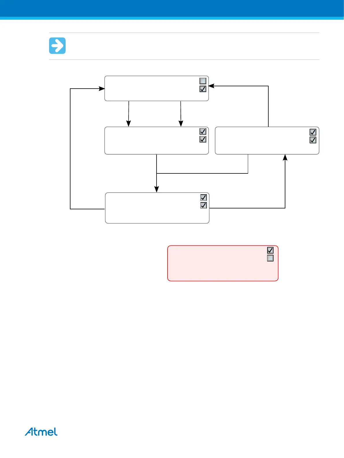
Figure 4-14. Understanding debugWIRE and the DWEN Fuse
Atmel Studio
start debug session
Power toggle
(latches debugWIRE state)
Studio "Disable debugWIRE and close"
(disables debugWIRE module temporarily
and then clears DWEN fuse using SPI)
atprogram dwdisable
(atprogram disables
debugWIRE module temporarily)
Clear DWEN fuse
using SPI
Set DWEN fuse
using SPI
Intermediate state 1:
Fuse DWEN set
Fuse SPIEN set* (NB!)
Module debugWIRE disabled until power toggle
You can: Toggle power
DWEN
SPIEN
Default state:
Fuse DWEN cleared
Fuse SPIEN set
Module debugWIRE disabled
You can: Access flash and fuses using SPI
DWEN
SPIEN
Debug state:
Fuse DWEN set
Fuse SPIEN set
Module debugWIRE enabled
You can: use debugWIRE
You cannot: Access fuses or flash using SPI
DWEN
SPIEN
Intermediate state 2:
Fuse DWEN set
Fuse SPIEN set
Module debugWIRE disabled
You can: Access fuses and flash using SPI
DWEN
SPIEN
Debug state (not recommended):
Fuse DWEN set
Fuse SPIEN cleared
Module debugWIRE enabled
You can: use debugWIRE
To access flash and fuses it is now necessary to
use the High-Voltage Programming interface
DWEN
SPIEN
4.4.17. TinyX-OCD (UPDI) Special Considerations
The UPDI data pin (UPDI_DATA) can be a dedicated pin or a shared pin, depending on the target AVR
device. A shared UPDI pin is 12V tolerant, and can be configured to be used as /RESET or GPIO. For
further details on how to use the pin in these configurations, see UPDI Physical Interface.
On devices which include the CRCSCAN module (Cyclic Redundancy Check Memory Scan) this module
should not be used in continuous background mode while debugging. The OCD module has limited
hardware breakpoint comparator resources, so BREAK instructions may be inserted into flash (software
breakpoints) when more breakpoints are required, or even during source-level code stepping. The CRC
module could incorrectly detect this breakpoint as a corruption of flash memory contents.
The CRCSCAN module can also be configured to perform a CRC scan before boot. In the case of a CRC
mismatch, the device will not boot, and appear to be in a locked state. The only way to recover the device
from this state is to perform a full chip erase and either program a valid flash image or disable the pre-
boot CRCSCAN. (A simple chip erase will result in a blank flash with invalid CRC, and the part will thus
still not boot.) Atmel Studio will automatically disable the CRCSCAN fuses when chip erasing a device in
this state.
Atmel Atmel-ICE [USER GUIDE]
Atmel-42330C-Atmel-ICE_User Guide-10/2016
48

Table of Contents

Question and Answer IconNeed help?

Do you have a question about the Atmel Atmel-ICE and is the answer not in the manual?

Atmel Atmel-ICE Specifications

General IconGeneral
BrandAtmel
ModelAtmel-ICE
CategoryMicrocontrollers
LanguageEnglish

Summary

Introduction to Atmel-ICE Features

Atmel-ICE Features Overview

Describes the key features of the Atmel-ICE development tool, including compatibility and supported interfaces.

Getting Started with Atmel-ICE

Atmel-ICE Full Kit Contents

Lists the items included in the Atmel-ICE full kit, essential for initial setup and operation.

Assembling the Atmel-ICE Unit

Provides instructions on how to connect cables and prepare the Atmel-ICE unit for use.

Connecting the Atmel-ICE to Target Devices

Connecting AVR and SAM Target Devices

Explains how to connect the Atmel-ICE to various target microcontroller devices.

Connecting to a JTAG Target

Details the procedure for connecting the Atmel-ICE to target devices using the JTAG interface.

On-chip Debugging Introduction

Introduction to On-chip Debugging

Introduces the concept of on-chip debugging and its role in development.

Atmel-ICE Software Integration

Atmel Studio Integration

Explains how to integrate and use the Atmel-ICE with the Atmel Studio IDE.

Advanced Debugging Techniques

debugWIRE Target Techniques

Covers specific techniques and considerations for debugging with the debugWIRE interface.

Release History and Known Issues

Firmware Release History

Lists past firmware versions and their associated changes and improvements.

Product Compliance Overview

Information regarding the product's compliance with RoHS, WEEE, CE, and FCC regulations.

Introduction to System Requirements

System Requirements for Atmel-ICE

Outlines the necessary software and hardware requirements for using the Atmel-ICE.

Getting Started with Atmel-ICE Kits

Atmel-ICE Kit Overview

Provides a diagrammatic overview of the different Atmel-ICE kit options and their components.

Opening the Atmel-ICE Unit

Details the procedure for safely opening the Atmel-ICE unit.

Connecting Atmel-ICE to Targets

Connecting AVR and SAM Target Devices

Explains how to connect the Atmel-ICE to various target microcontroller devices.

Connecting to a JTAG Target

Details the procedure for connecting the Atmel-ICE to target devices using the JTAG interface.

Connecting to an SWD Target

Explains how to connect the Atmel-ICE to target devices using the SWD interface.

On-chip Debugging for SAM Devices

Introduction to On-chip Debugging

Introduces the concept of on-chip debugging and its role in development.

SAM Devices with JTAG/SWD

Details on-chip debugging for SAM devices using JTAG and SWD interfaces.

ARM CoreSight Components Description

Describes the CoreSight components used in Atmel ARM Cortex-M microcontrollers.

AVR UC3 Debugging with JTAG/aWire

Atmel AVR UC3 On-chip Debug System

Explains the on-chip debug system for Atmel AVR UC3 microcontrollers.

JTAG Physical Interface for AVR UC3

Details the physical JTAG interface for AVR UC3 devices.

tinyAVR, megaAVR, XMEGA Device Interfaces

JTAG Physical Interface for AVR Devices

Describes the JTAG physical interface for tinyAVR, megaAVR, and XMEGA devices.

Connecting to a JTAG Target

Guides on connecting the Atmel-ICE to JTAG targets for these device families.

Connecting to an SPI Target

Explains how to connect the Atmel-ICE to target devices using the SPI interface.

megaAVR Debugging Considerations

Software Breakpoints for megaAVR

Discusses limitations and usage of software breakpoints for megaAVR devices.

JTAG Clock Frequency for megaAVR

Details clock frequency considerations for JTAG debugging of megaAVR devices.

AVR XMEGA Debugging Considerations

OCD and Clocking for XMEGA

Explains OCD clocking behavior for XMEGA devices during stopped mode.

Hardware Breakpoints for XMEGA

Details the hardware breakpoint capabilities and restrictions for XMEGA devices.

debugWIRE Special Considerations

debugWIRE Enable Fuse (DWEN) Management

Details the importance and usage of the DWEN fuse for enabling debugwire functionality.

Atmel-ICE Hardware Description

Atmel-ICE Architecture Overview

Provides a block diagram and explanation of the Atmel-ICE's internal architecture.

Software Integration with Atmel Studio

Atmel Studio Integration Guide

Explains how to integrate and use the Atmel-ICE with the Atmel Studio IDE.

Programming Options Configuration

Details the configuration options for programming Atmel AVR and SAM devices.

Debug Options Configuration

Covers important configuration options for debugging within Atmel Studio.

Advanced Debugging Techniques

Atmel AVR UC3 Target Techniques

Discusses advanced debugging techniques applicable to Atmel AVR UC3 targets.

debugWIRE Target Techniques

Covers specific techniques and considerations for debugging with the debugwire interface.

Release History and Known Issues

Firmware Release History Details

Lists past firmware versions and their associated changes and improvements.

Known Issues with Atmel-ICE

Details known issues and limitations with the Atmel-ICE hardware and firmware.

Product Compliance Information

RoHS and WEEE Compliance

Information regarding the product's compliance with RoHS and WEEE directives.

CE and FCC Compliance

Details the product's compliance with CE and FCC regulations for electromagnetic emissions.

Revision History of Document

Related product manuals