• TMS and TCK are connected in parallel; TDI and TDO are connected in a serial chain.
• nSRST on the Atmel-ICE probe must be connected to RESET on the devices if any of the devices
in the chain disables its JTAG port
• "Devices before" refers to the number of JTAG devices that the TDI signal has to pass through in
the daisy chain before reaching the target device. Similarly "devices after" is the number of devices
that the signal has to pass through after the target device before reaching the Atmel-ICE TDO pin.
• "Instruction bits "before" and "after" refers to the total sum of all JTAG devices' instruction register
lengths, which are connected before and after the target device in the daisy chain
• The total IR length (instruction bits before + Atmel target device IR length + instruction bits after) is
limited to a maximum of 256 bits. The number of devices in the chain is limited to 15 before and 15
after.
Tip:
Daisy chaining example: TDI → ATmega1280 → ATxmega128A1 → ATUC3A0512 → TDO.
In order to connect to the Atmel AVR XMEGA
®
device, the daisy chain settings are:
• Devices before: 1
• Devices after: 1
• Instruction bits before: 4 (8-bit AVR devices have 4 IR bits)
• Instruction bits after: 5 (32-bit AVR devices have 5 IR bits)
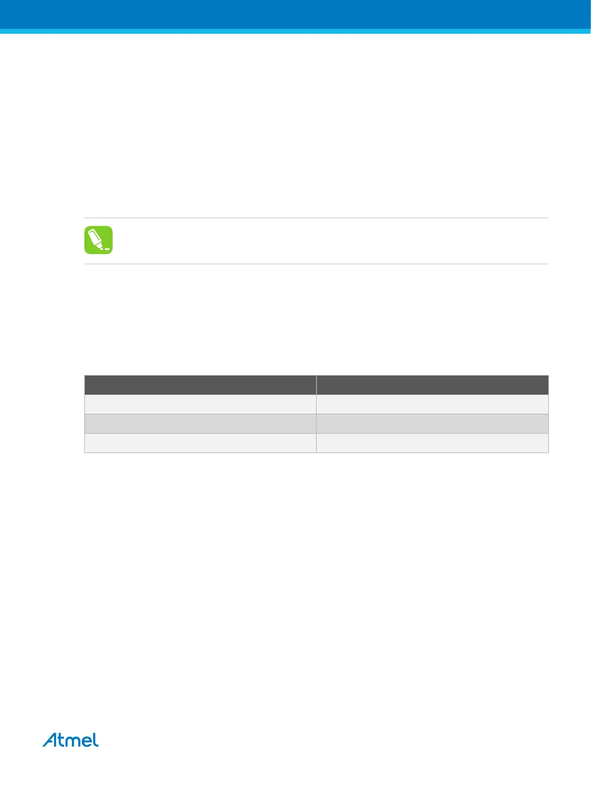
Table 4-6. IR Lengths of Atmel MCUs
Device type IR length
AVR 8-bit 4 bits
AVR 32-bit 5 bits
SAM 4 bits
4.3.3. Connecting to a JTAG Target
The Atmel-ICE is equipped with two 50-mil 10-pin JTAG connectors. Both connectors are directly
electrically connected, but conform to two different pinouts; the AVR JTAG header and the ARM Cortex
Debug header. The connector should be selected based on the pinout of the target board, and not the
target MCU type - for example a SAM device mounted in an AVR STK600 stack should use the AVR
header.
The recommended pinout for the 10-pin AVR JTAG connector is shown in Figure 4-6.
The recommended pinout for the 10-pin ARM Cortex Debug connector is shown in Figure 4-2.
Direct connection to a standard 10-pin 50-mil header
Use the 50-mil 10-pin flat cable (included in some kits) to connect directly to a board supporting this
header type. Use the AVR connector port on the Atmel-ICE for headers with the AVR pinout, and the SAM
connector port for headers complying with the ARM Cortex Debug header pinout.
The pinouts for both 10-pin connector ports are shown below.
Connection to a standard 10-pin 100-mil header
Atmel Atmel-ICE [USER GUIDE]
Atmel-42330C-Atmel-ICE_User Guide-10/2016
32

 Loading...


