86
8126F–AVR–05/12
ATtiny13A
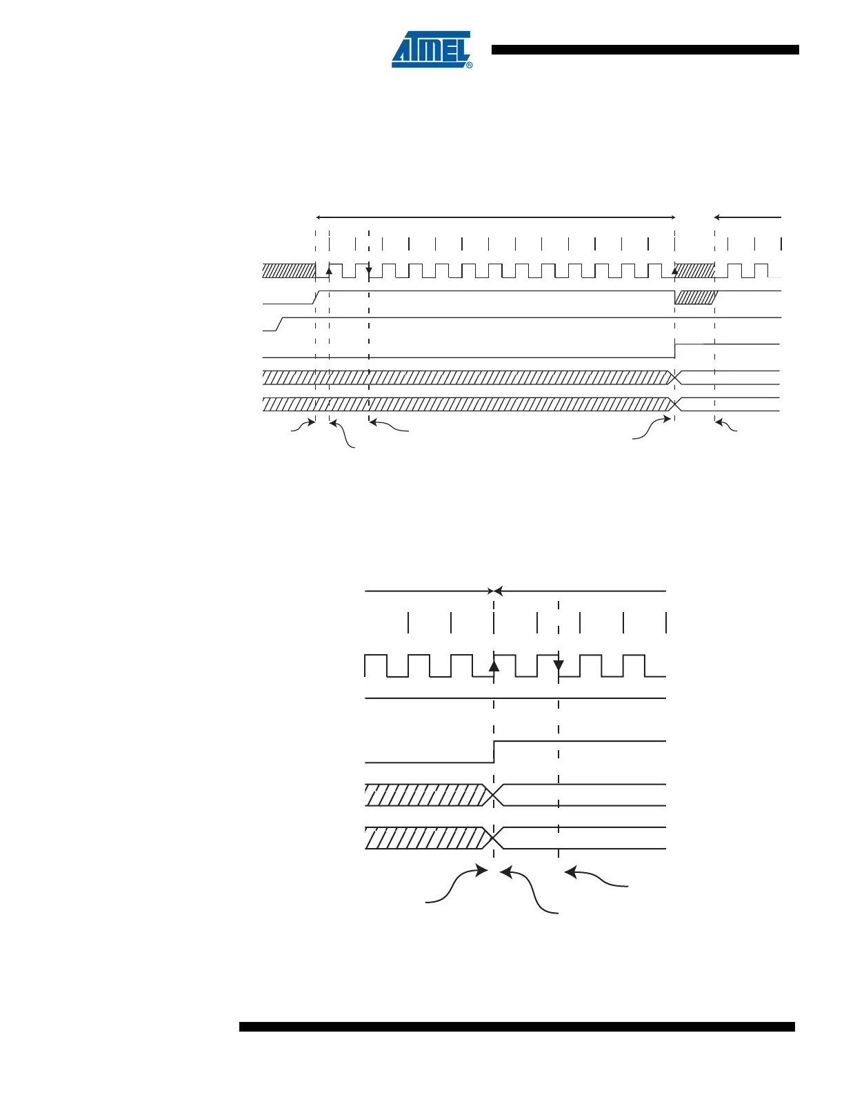
When Auto Triggering is used, the prescaler is reset when the trigger event occurs, as shown in
Figure 14-6 below. This assures a fixed delay from the trigger event to the start of conversion. In
this mode, the sample-and-hold takes place two ADC clock cycles after the rising edge on the
trigger source signal. Three additional CPU clock cycles are used for synchronization logic.
Figure 14-6. ADC Timing Diagram, Auto Triggered Conversion
In Free Running mode, a new conversion will be started immediately after the conversion com-
pletes, while ADSC remains high.
Figure 14-7. ADC Timing Diagram, Free Running Conversion
1 2 3 4 5 6 7 8
9
10 11 12 13
Sign and MSB of Result
LSB of Result
ADC Clock
Trigger
Source
ADIF
ADCH
ADCL
Cycle Number
12
One Conversion Next Conversion
Conversion
Complete
Prescaler
Reset
ADATE
Prescaler
Reset
Sample &
Hold
MUX and REFS
Update
11 12 13
Sign and MSB of Result
LSB of Result
ADC Clock
ADSC
ADIF
ADCH
ADCL
Cycle Number
12
One Conversion Next Conversion
34
Conversion
Complete
Sample & Hold
MUX and REFS
Update