107
ATtiny26(L)
1477G–AVR–03/05
Memory
Programming
Program and Data
Memory Lock Bits
The ATtiny26 provides two Lock bits which can be left unprogrammed (“1”) or can be
programmed (“0”) to obtain the additional features listed in Table 49. The Lock bits can
only be erased to “1” with the Chip Erase command.
Note: 1. “1” means unprogrammed, “0” means programmed
Notes: 1. Program the Fuse bits before programming the Lock bits.
2. “1” means unprogrammed, “0” means programmed
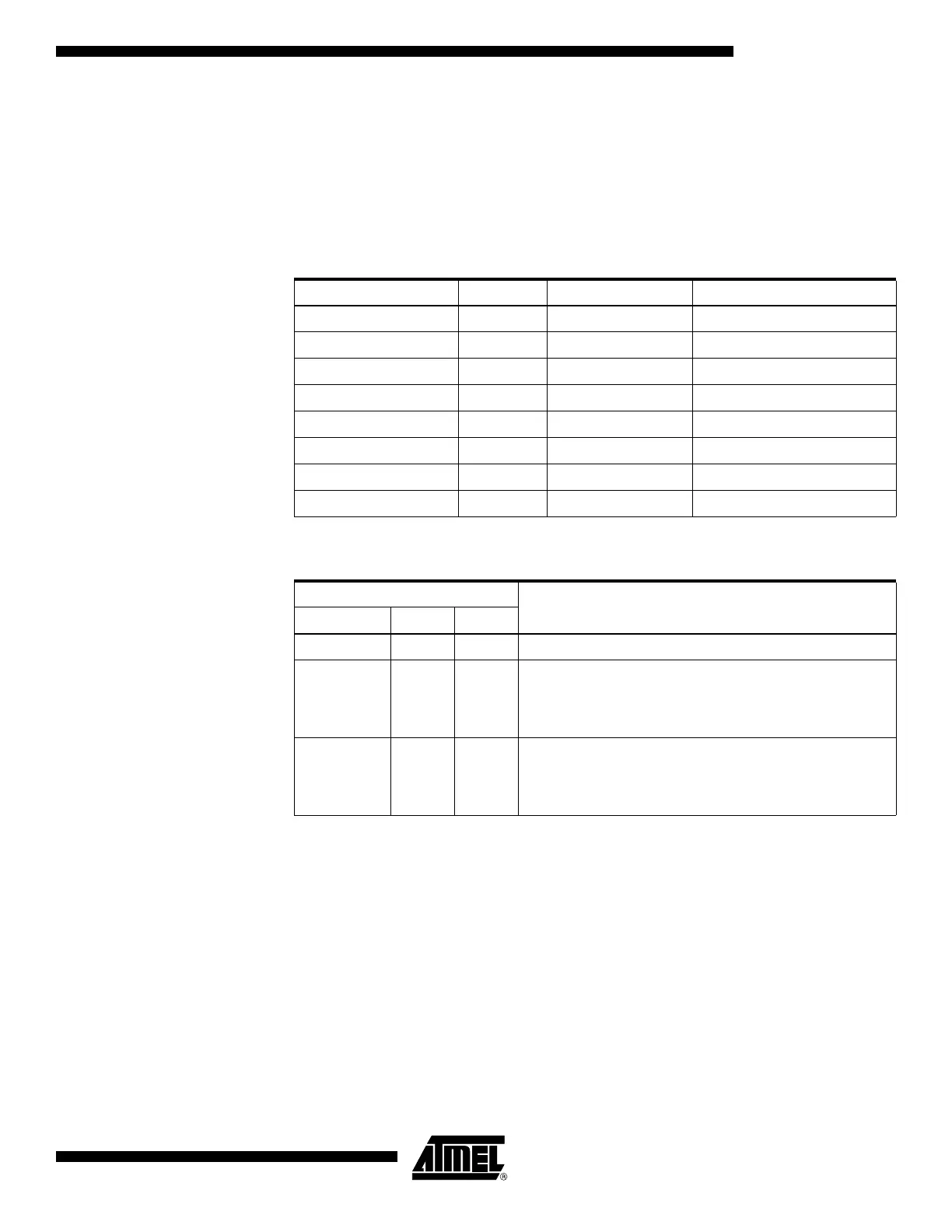
Table 48. Lock Bit Byte
(1)
Lock Bit Byte Bit No Description Default Value
7 – 1 (unprogrammed)
6 – 1 (unprogrammed)
5 – 1 (unprogrammed)
4 – 1 (unprogrammed)
3 – 1 (unprogrammed)
2 – 1 (unprogrammed)
LB2 1 Lock bit 1 (unprogrammed)
LB1 0 Lock bit 1 (unprogrammed)
Table 49. Lock Bit Protection Modes
Memory Lock Bits
Protection TypeLB Mode LB2
(2)
LB1
(2)
1 1 1 No memory lock features enabled.
210
Further programming of the Flash and EEPROM is
disabled in parallel and serial programming mode. The
Fuse bits are locked in both serial and parallel
programming mode.
(1)
300
Further programming and verification of the Flash and
EEPROM is disabled in parallel and serial programming
mode. The Fuse bits are locked in both serial and parallel
programming mode.
(1)

 Loading...


