17
ATtiny26(L)
1477G–AVR–03/05
The five different addressing modes for the data memory cover: Direct, Indirect with Dis-
placement, Indirect, Indirect with Pre-decrement, and Indirect with Post-increment. In
the Register File, registers R26 to R31 feature the indirect addressing pointer registers.
The direct addressing reaches the entire data space. The Indirect with Displacement
mode features a 63 address locations reach from the base address given by the Y- or Z-
register.
When using register indirect addressing modes with automatic pre-decrement and post-
increment, the address registers X, Y, and Z are decremented and incremented.
The 32 general purpose working registers, 64 I/O Registers and the 128 bytes of inter-
nal data SRAM in the ATtiny26(L) are all accessible through all these addressing
modes.
See “Program and Data Addressing Modes” on page 10 for a detailed description of the
different addressing modes.
EEPROM Data Memory The ATtiny26(L) contains 128 bytes of data EEPROM memory. It is organized as a sep-
arate data space, in which single bytes can be read and written (see “Memory
Programming” on page 107). The EEPROM has an endurance of at least 100,000
write/erase cycles per location.
EEPROM Read/Write Access The EEPROM Access Registers are accessible in the I/O space.
The write access time is typically 8.3 ms. A self-timing function lets the user software
detect when the next byte can be written. A special EEPROM Ready Interrupt can be
set to trigger when the EEPROM is ready to accept new data.
An ongoing EEPROM write operation will complete even if a reset condition occurs.
In order to prevent unintentional EEPROM writes, a two state write procedure must be
followed. Refer to the description of the EEPROM Control Register for details on this.
When the EEPROM is written, the CPU is halted for two clock cycles before the next
instruction is executed.
When the EEPROM is read, the CPU is halted for four clock cycles before the next
instruction is executed.
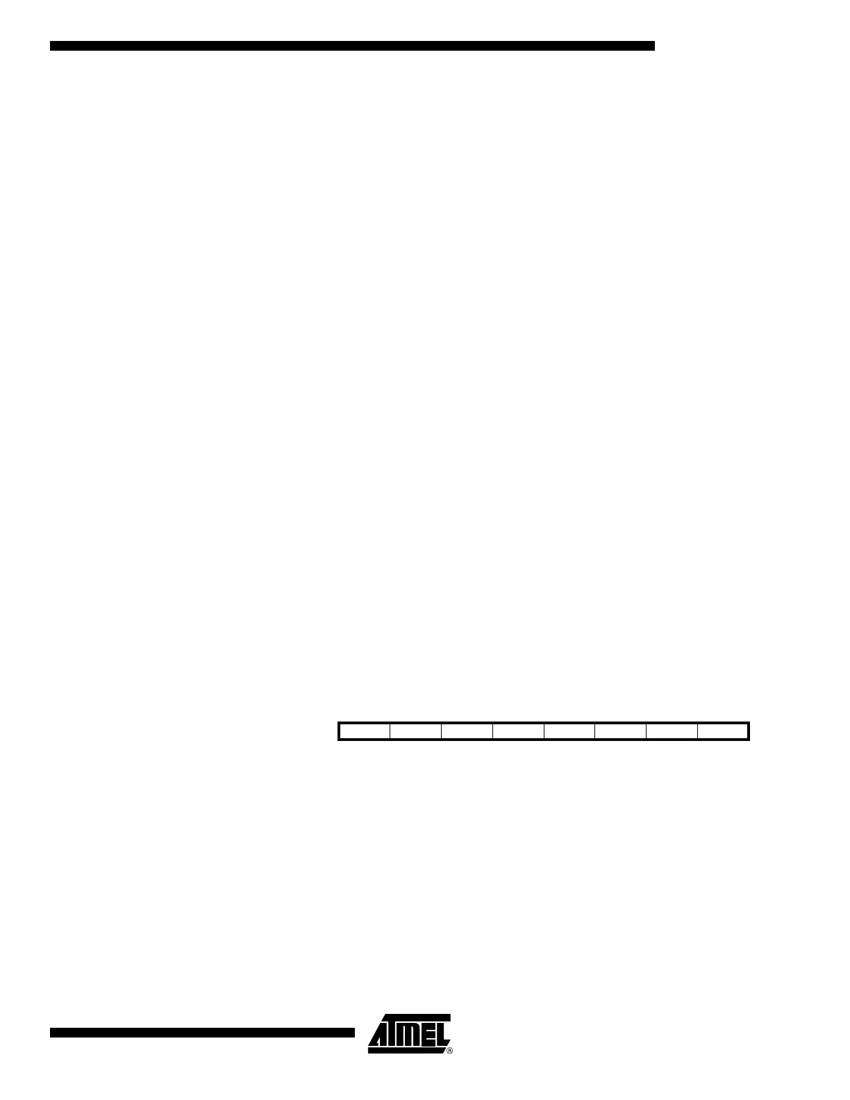
EEPROM Address Register –
EEAR
• Bit 7 – RES: Reserved Bits
This bit are reserved bit in the ATtiny26(L) and will always read as zero.
• Bit 6..0 – EEAR6..0: EEPROM Address
The EEPROM Address Register – EEAR – specifies the EEPROM address in the 128
bytes EEPROM space. The EEPROM data bytes are addressed linearly between 0 and
127. The initial value of EEAR is undefined. A proper value must be written before the
EEPROM may be accessed.
Bit 76543210
$1E ($3E) – EEAR6 EEAR5 EEAR4 EEAR3 EEAR2 EEAR1 EEAR0 EEAR
Read/Write R R/W R/W R/W R/W R/W R/W R/W
Initial Value0XXXXXXX