31
ATtiny26(L)
1477G–AVR–03/05
System Control and
Reset
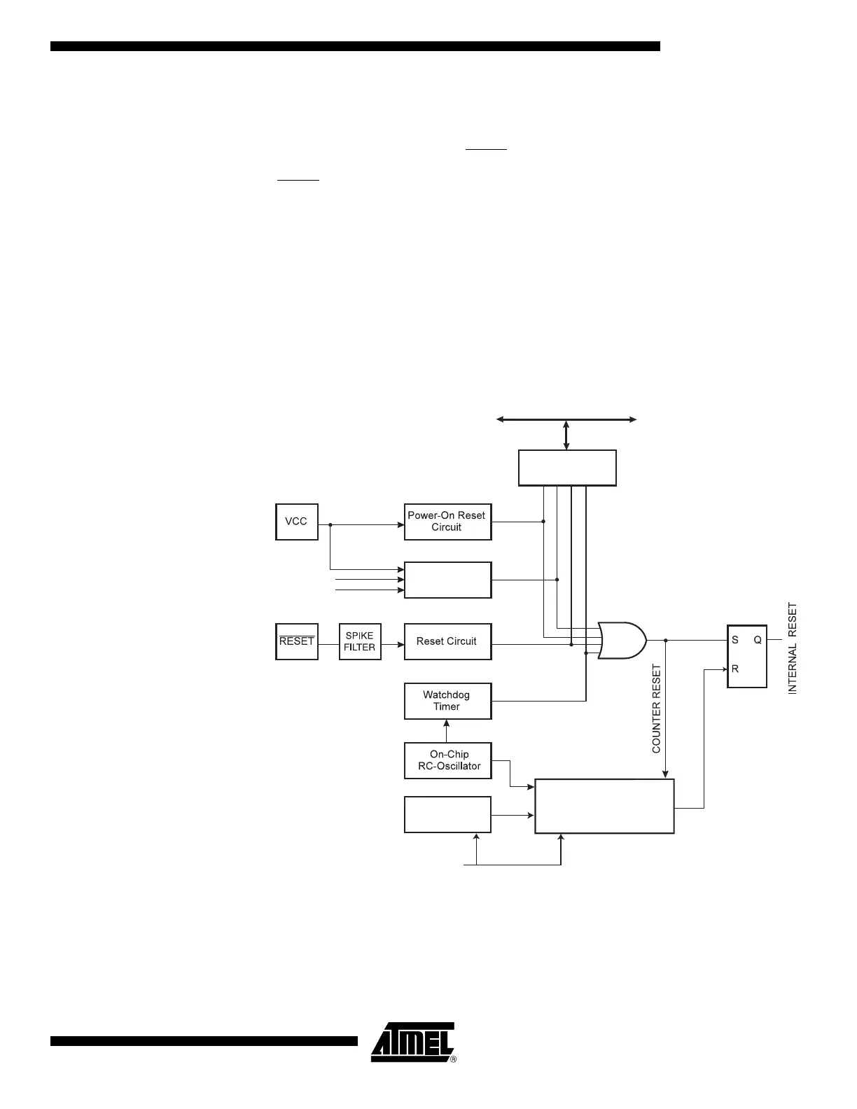
The ATtiny26(L) provides four sources of reset:
•
Power-on Reset. The MCU is reset when the supply voltage is below the Power-on Reset
threshold (V
POT
).
• External Reset. To use the PB7/RESET pin as an External Reset, instead of I/O pin,
unprogram (“1”) the RSTDISBL Fuse. The MCU is reset when a low level is present on the
RESET
pin for more than 50 ns.
• Watchdog Reset. The MCU is reset when the Watchdog timer period expires and the
Watchdog is enabled.
• Brown-out Reset. The MCU is reset when the supply voltage V
CC
is below the Brown-out
Reset threshold (V
BOT
).
During reset, all I/O Registers are then set to their initial values, and the program starts
execution from address $000. The instruction placed in address $000 must be an RJMP
– Relative Jump – instruction to the reset handling routine. If the program never enables
an interrupt source, the interrupt vectors are not used, and regular program code can be
placed at these locations. Figure 25 shows the reset logic for the ATtiny26(L). Table 16
shows the timing and electrical parameters of the reset circuitry for ATtiny26(L).
Figure 25. Reset Logic for the ATtiny26(L)
MCU Status
Register (MCUSR)
Brown-Out
Reset Circuit
BODEN
BODLEVEL
Delay Counters
CKSEL[3:0]
CK
TIMEOUT
WDRF
BORF
EXTRF
PORF
DATA B U S
Clock
Generator