118
ATtiny26(L)
1477G–AVR–03/05
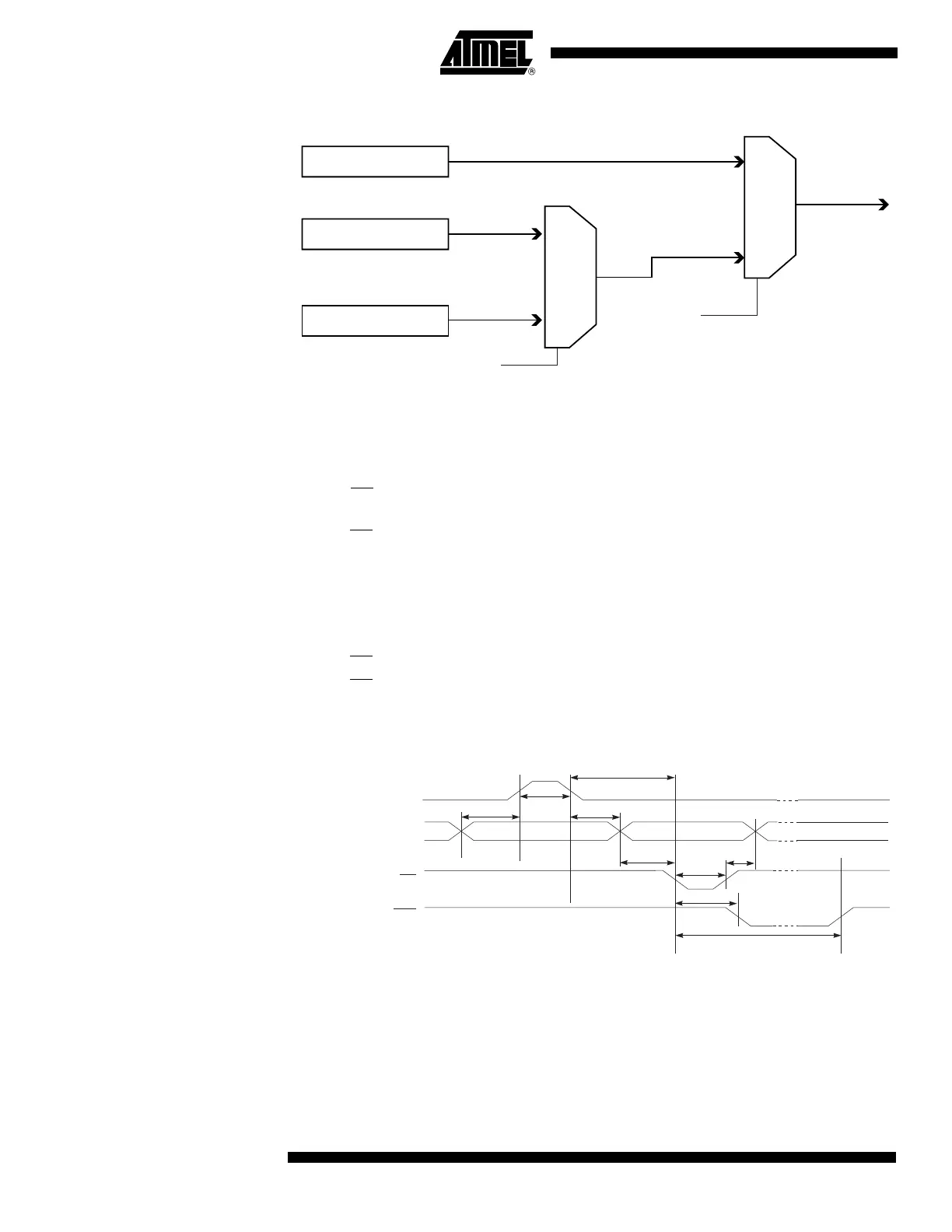
Figure 63. Mapping Between BS1, BS2 and the Fuse- and Lock-bits During Read
Reading the Signature Bytes The algorithm for reading the Signature bytes is as follows (refer to Programming the
Flash for details on Command and Address loading):
1. A: Load Command “0000 1000”.
2. B: Load Address Low Byte ($00 - $02).
3. Set OE
to “0” and BS1 to “0”. The selected Signature byte can now be read at
DATA.
4. Set OE
to “1”.
Reading the Calibration Byte The algorithm for reading the Calibration byte is as follows (refer to Programming the
Flash for details on Command and Address loading):
1. A: Load Command “0000 1000”.
2. B: Load Address Low Byte.
3. Set OE
to “0” and BS1 to “1”. The Calibration byte can now be read at DATA.
4. Set OE
to “1”.
Parallel Programming
Characteristics
Figure 64. Parallel Programming Timing, Including some General Timing
Requirements
Fuse Low Byte
Lock Bits
0
1
BS2
Fuse High Byte
0
1
BS1
DATA
Data & Contol
(DATA, XA0, XA1/BS2
PAGEL/BS1)
XTAL1
t
XHXL
t
WLWH
t
DVXH
t
XLDX
t
WLRH
WR
RDY/BSY
t
XLWL
t
WLBX
t
BVWL
WLRL

 Loading...


