Analog Fast Track Guide 2. Installing the MediaPack
Version 5.0 15 October 2006
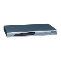
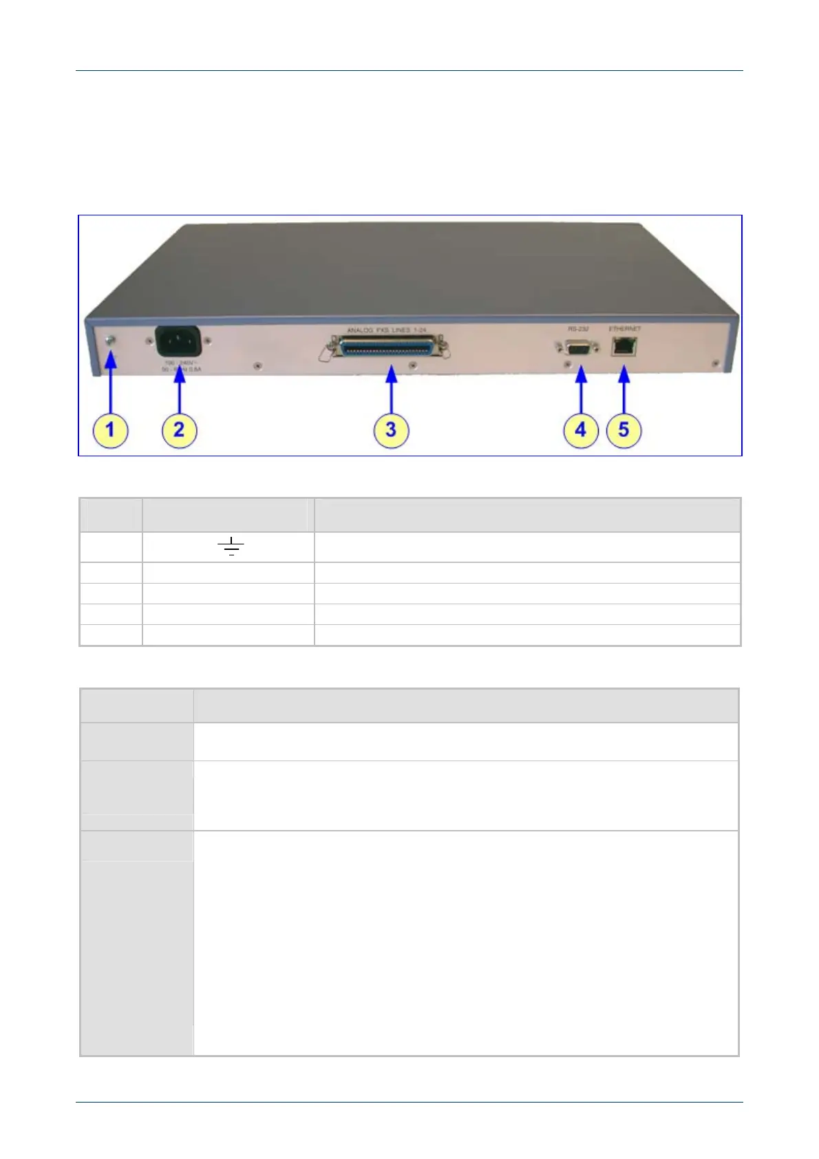
2.2.4 Cabling the MP-124
Figure 2-11 illustrates the rear panel of the MP-124. For descriptions of the MP-124 rear panel
components, refer to Table 2-5.
Cable your MP-124 according to each section of Table 2-6.
Figure 2-11: MP-124 (FXS) Rear Panel Connectors
Table 2-5: MP-124 Rear Panel Component Descriptions
Item # Label Component Description
1
Protective earthing screw (mandatory for all installations).
2
100-250 V~ 50 - 60 Hz 2A
AC power supply socket.
3
ANALOG FXS LINES 1 –24
50-pin Telco for 1 to 24 analog lines.
5
RS-232
9-pin RS-232 status port.
6
ETHERNET
10/100 Base-TX Ethernet connection.
Table 2-6: MP-124 Cables and Cabling Procedure
Cable Cabling Procedure
Protective
earthing strap
Connect an earthed strap to the chassis protective earthing screw and fasten it securely
according to the safety standards.
RJ-45 Ethernet
cable
Connect the MP-124 Ethernet connection directly to the network using a crossover
RJ-45 Ethernet cable. For connector pinouts, refer to Figure 2-12 below.
Note that when assigning an IP address to the MP-124 using HTTP (under Step 1 in
Section 3.1.1), you may be required to disconnect this cable and re-cable it differently.
50-pin Telco
cable (MP-124
devices only).
An Octopus
cable is not
included with
the MP-124
package.
Refer to the MP-124 Safety Notice below.
1. Wire the 50-pin Telco connectors according to the pinouts in Figure 2-13 on page 16,
and Figure 2-14 on page 17.
2. Attach each pair of wires from a 25-pair Octopus cable to its corresponding socket on
the MDF Adaptor Block’s rear.
3. Connect the wire-pairs at the other end of the cable to a male 50-pin Telco
connector.
4. Insert and fasten this connector to the female 50-pin Telco connector on the
MP-124 rear panel (labeled Analog Lines 1-24).
5. Connect the telephone lines from the Adaptor Block to a fax machine, modem, or
telephones by inserting each RJ-11 connector on the 2-wire line cords of the POTS
phones into the RJ-11 sockets on the front of an MDF Adaptor Block as shown in
Figure 2-14 on page 17.
http://ArtTel.ru
 Loading...