3 Water Level Control
Page 46 Mk8 MM Expansion Features Installation and Set-Up Guide 04.09.2016
3.4.9 Configuration
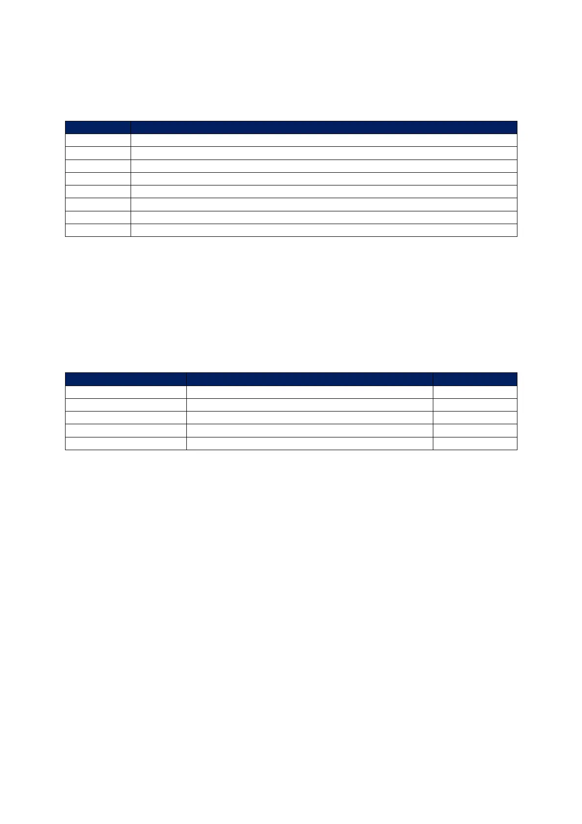
The table below shows the terminals allocated on the MM for the capacitance probes.
Terminal Description
1P+ +9V supply to capacitance probe 1
1P- 0V supply to capacitance probe 1
1T+ Digital communications connections from capacitance probe 1
1T- Digital communications connections from capacitance probe 1
2P+ +9V supply to capacitance probe 2
2P- 0V supply to capacitance probe 2
2T+ Digital communications connections from capacitance probe 2
2T- Digital communications connections from capacitance probe 2
When wiring the capacitance probes, the screen is connected through the casing of the lead and
through the probe; therefore the flying lead should be connected to the MM without a screen. The
screen should be carried through until the connection to the MM; the screen should not be connected
to the S terminal.
The table below shows the expansion options to be set when using the capacitance probes with the
MM for water level detection.
Expansion Option Description Setting
1 Water level control function 1
3 Capacitance probes 1 or 2
27 Probe mismatch threshold As required
28 Capacitance probe still water threshold As required
29 Capacitance probe filter time As required

 Loading...

