5 Bottom Blowdown
Page 88 Mk8 MM Expansion Features Installation and Set-Up Guide 04.09.2016
5.3 Installation Guidance
The bottom blowdown valve must be sized appropriately for blowdown rate required, which will be
affected by the boiler pressure, size of blowdown line and blowdown line length from the boiler to the
bottom blowdown vessel. The blowdown rate that is required for that boiler will vary according to the
operating conditions, contaminants in the feed water and boiler design.
The bottom blowdown valve must be installed along the blowdown pipeline according
to local code and regulations. It is the responsibility of the factory trained technician or
engineer to configure the bottom blowdown timings according to the specifications
given by the boiler manufacturer.
In multi-boiler systems where a bottom blowdown valve is fitted to each boiler, enabling Autoflame
sequencing in option 16 will ensure that only boiler in that loop blows down at a given time. If a
blowdown time is set the same on all the MMs in a sequencing loop, the MM with the lowest ID
complete its blowdown first, followed by the rest of the MMs, sequentially. If Autoflame sequencing is
not used for multi-boiler system requiring bottom blowdown in the UK, then valves must be interlocked;
this ensures that only boiler can be blown down at one time. Please see local code and regulation on
bottom blowdown in multi-boiler systems.
The Autoflame bottom blowdown module (part number BBC70004) has a built in lithium ion battery,
so should a power failure to the module, bottom blowdown fault or MM error occur, the battery will
drive the servomotor to the closed position. The servomotor is powered by 24V DC from the bottom
blowdown module.
5.3.1 Bottom Blowdown Valve
Water valves are universal for feed water, TDS, and bottom blowdown function. ½” and ¾” water
level valves must be used with large servomotors. Industrial unic 05 servomotors must be used 1” and
1 ½”, and industrial unic 10 for 2” water valves. for water valves bigger than ¾”.
Maximum operating pressure: 29 Bar (425 PSI)
Maximum operating temperature: 235
O
C (455
O
F)
Please see section 3.2.1 for more information on water valves.
Note: Please Valves and Servomotors manual for water level valve dimensions, drawings and
information on service and maintenance.
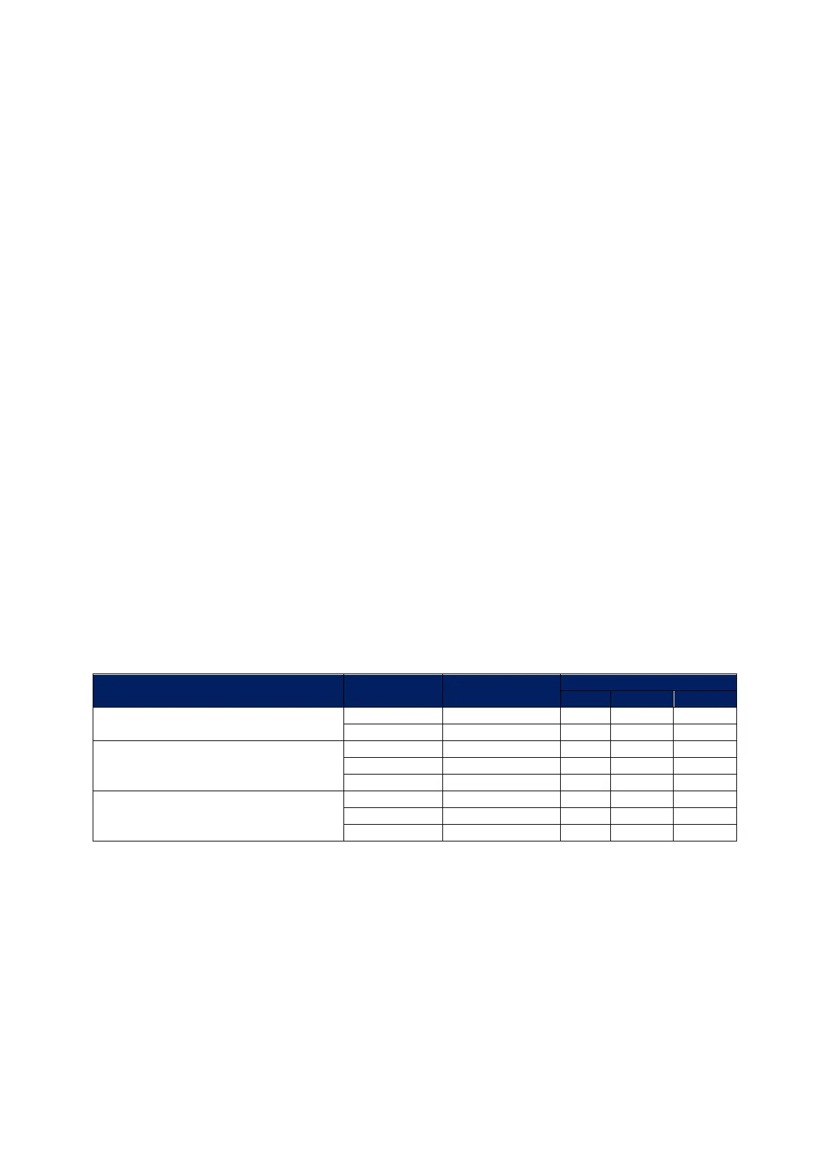
Valve Type Size Part No.
Servomotor
Large Unic 05 Unic 10
Threaded BSP/ NPT
15mm (½”) WLCVO15 •
20mm (¾”) WLCVO20 •
Flanged PN40
25mm (1”) WLCVO25/FL •
40mm (1 ½”) WLCVO40/FL •
50mm (2”) WLCVO50/FL •
Flanged ANSI 300lb
25mm (1”) WLCVO25/FLU •
40mm (1 ½”) WLCVO40/FLU •
50mm (2”) WLCVO50/FLU •

 Loading...

