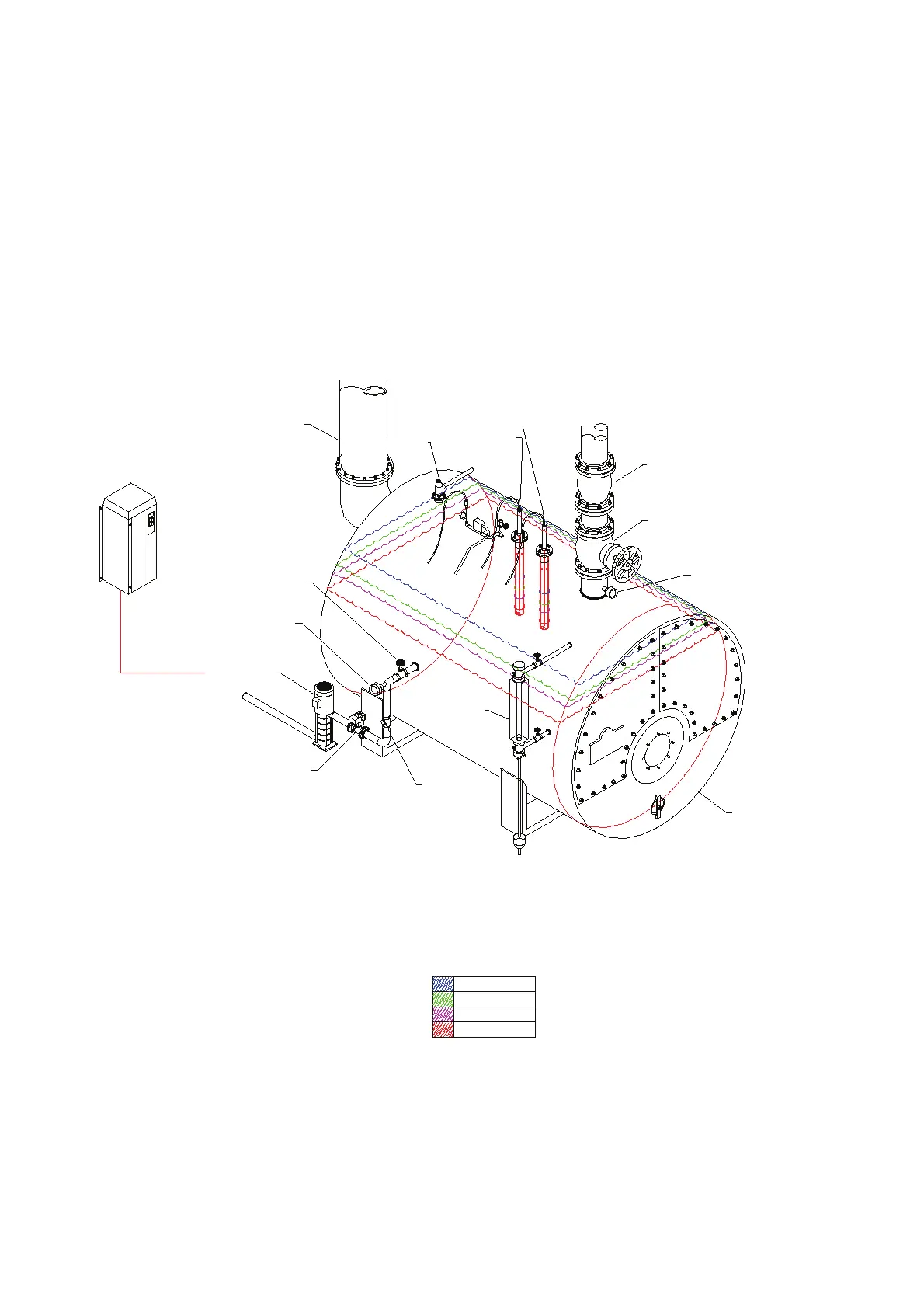
HIGH WATER
REQUIRED LEVEL
1st LOW WATER
2nd LOW WATER
LEVEL PROBES INSTALLED DIRECTLY TO BOILER SHELL
NON-RETURN
VALVE
STEAM BOILER
SIGHT GLASS
AUTOFLAME FEED WATER VALVE CONTROLLED
BY A SERVOMOTOR (OPTIONAL V.S.D.)
FEED WATER PUMP
ISOLATION VALVE
AUTOFLAME FEED WATER
TEMP. SENSOR (PT1000)
OPTIONAL V.S.D. CONTROL
FOR FEED WATER PUMP
FLUE
SAFETY VALVE
CAPACITANCE
PROBES
STEAM NON-RETURN VALVE
STEAM FLOW VALVE/ CROWN VALVE
AUTOFLAME STEAM TEMP. SENSOR
3 Water Level Control
Page 42 Mk8 MM Expansion Features Installation and Set-Up Guide 04.09.2016
3.4.6 Capacitance Probe – Internally Mounted Pots
Please see section 3.4.4 for installation safety guidelines.
If the probes are mounted directly into the boiler shell it is important to lag the flanges in order to avoid
overheating of the electronics. It is recommended that they are not installed too close to the steam off-
take and safety valve connection, but also not too close to the boiler end plates. If possible, they
should be installed near the sight gauge glass.

 Loading...

