3 Water Level Control
04.09.2016 Mk8 MM Expansion Features Installation and Set-Up Guide Page 51
3.5.5 Configuration
The table below shows the terminals allocated on the MM for the 2
nd
low safety probe.
Terminal Description
5T+ Digital communication connections from 2
nd
low resistance probe
5T- Digital communication connections from 2
nd
low resistance probe
4P+ +12V supply to 2
nd
low resistance probe
4P- 0V supply to 2
nd
low resistance probe
The screen is connected through the casing of the flying lead supplied with the 2
nd
low safety probe.
When connecting the flying lead to the MM, do not wire a screen at the MM.
The table below shows the expansion options to be set when using the 2
nd
low probe with the MM.
Expansion Option Description Setting
1 Water level control function 1
6 Second Low Probe 1
Note: 2
nd
low probe can only be used in conjunction with an analogue sensing device such as two
capacitance probes or one capacitance and an external level sensor at minimum; please see section
3.3 Ways of Level Sensing for more information.
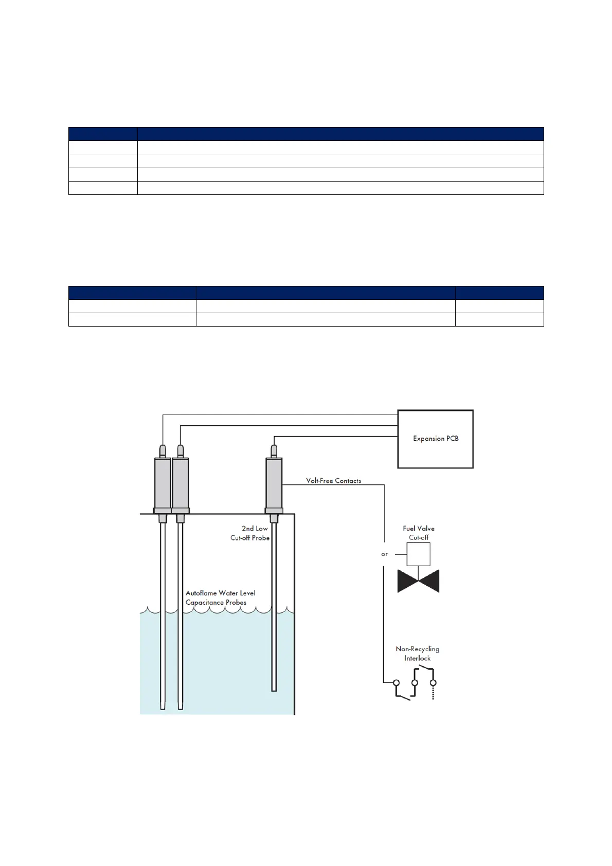
Figure 3.5.5.i 2
nd
Low Probe Installation Example
To install the 2
nd
low probe, no commissioning is required; just simply the probe in expansion option 6.
The bottom of the 2
nd
low probe should be at the capacitance probes/external level sensor
commissioned 2
nd
low level or higher.

 Loading...

