Owner Installation Instructions GDO-10V3L2 Toro
™
9
6.4 Installing The Wall Mounted Control Unit
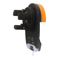
a. Remove the face cover from the wall mount control unit
3
.
b. Affix the wall mount control unit
3
at a height of 1.5 metres within sight of the door but away from moving parts.
Make sure this location of the wall control unit is out of reach of children and convenient to the customer.
c. Replace the face cover.
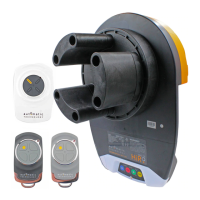
d. Connect the network cable
2
from the wall control unit to the GDO-10V3L2 powerhead unit
1
and secure with
p clips
7
.
e. Connect the power cord to a suitable power point, but DO NOT SWITCH ON. Secure the power cord away from
any moving object (e.g. the door) with the cable clips.
f. With the opener still disengaged, pull the door up and down to make sure it runs freely.
Fig 6.1
Fig 6.2
Fig 6.3
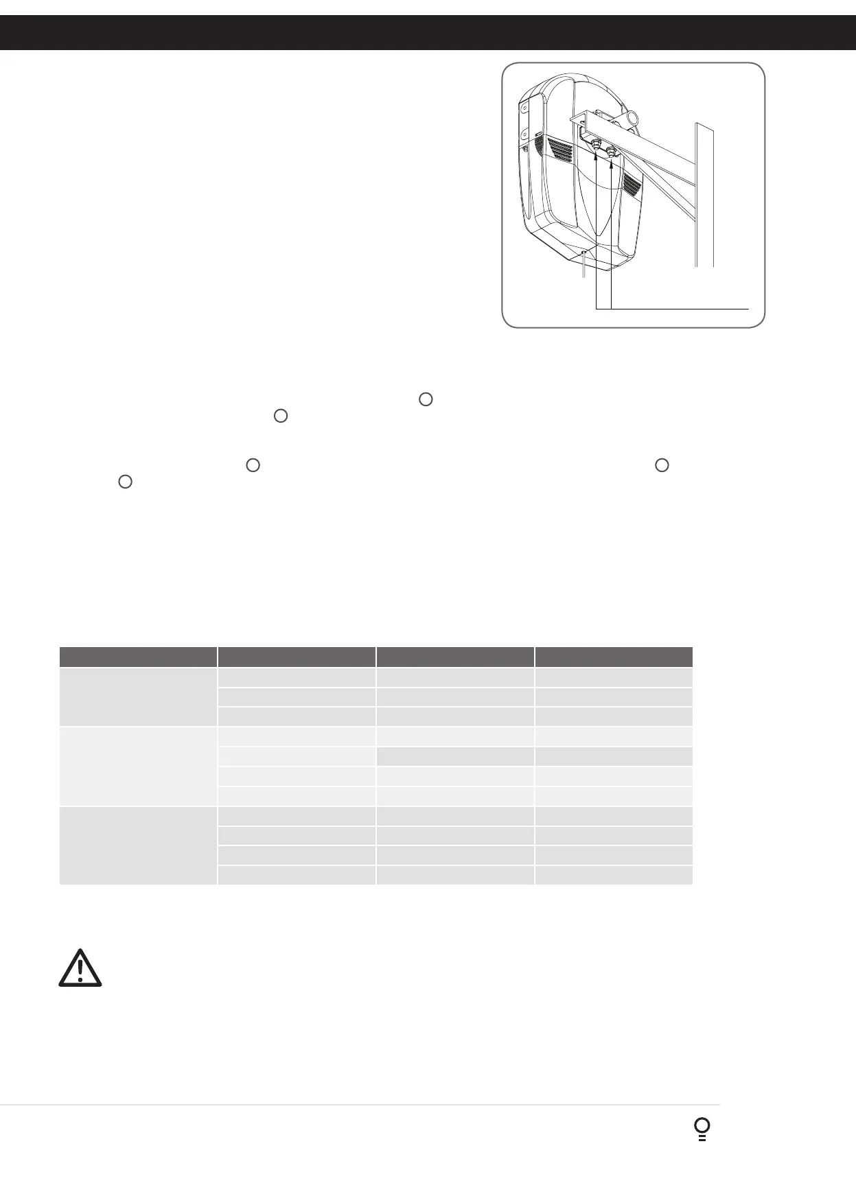
Tighten Nuts
7. Programming The Opener
The three most common programs are;
Program Menu’s required Function Section
Dead Man Set Up Menu 10.1 Setting the Limits 11.1
Safety Obstruction Force 12.1 and 12.2
Menu 1 Coding the Transmitter 13.1
Automated Set Up Menu 10.1 Setting the Limits 11.1
Safety Obstruction Force 12.1 and 12.2
Menu 1 Coding the Transmitter 13.1
Menu 6.1 Safety Close Mode 16.1
Automated Set Up with
Safety Beams
Menu 10.1 Setting the Limits 11.1
Safety Obstruction Force 12.1 and 12.2
Menu 1 Coding the Transmitter 13.1
Menu 3 Auto Close Times 16.3, 16.4 and 16.5
For the Dead Man Set Up and the Automated Set Up the door can not be closed by Auto-Close or by transmitters. When
Safety Beams are not installed, the controller will display the following message;
ATTENTION! No Safety Beams have been detected. “Safety Close’ mode has been turned on. See
Manual for details.
Press SET to continue.
If the closing force as measured on the bottom of the door is over 400N (40kg), a Safety Beam must be installed. The
Safety Close mode can be turned off by changing the parameter in menu 6.1 (Section 16.1).
NOTE: Fitting Safety Beams enables the Auto-Close feature to become active.
d. Re-attach the door bracket using your reference marks as a guide
and tighten the bolts. Ensure that the slots in the mounting bracket
of the opener align with the slots in the door bracket, otherwise
the door bracket may have to be relocated. If the bracket cannot
be relocated, the opener may be fitted onto the axle using the
opener’s saddle and bolts as follows:
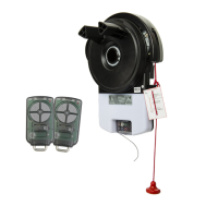
i. Using your reference marks as a guide, sit the opener on
the door mounting bracket and secure with the opener’s
bolts and saddle and tighten firmly (Fig. 6.3).
ii. Adjust the door position (if necessary) on the brackets so
that the door feeds smoothly into the guides. Make sure
that the centre of the door doesn’t hit the lintel and that
the curtain is not pushed forward hard into the guide.
e. Remove the support and safety ropes.
NOTE - If the manual release handle is more than 1.8 metres from floor
level when the opener is installed, extend the handle to a height less
than 1.8 metres.