MDF/lDF DESIGN: DEFINITY GENERIC 2 WITH UNIVERSAL MODULES
7-21
Use the type-2 frame (described earlier in this chapter under
Recommended Frames for Terminal Blocks)
to design a zoned MDF that is terminating up to 16 modules. Table 7-7,
Module Allocation per Zone
with Type-2 Frame,
shows the number of modules allocation per zone when you design an MDF with a
1
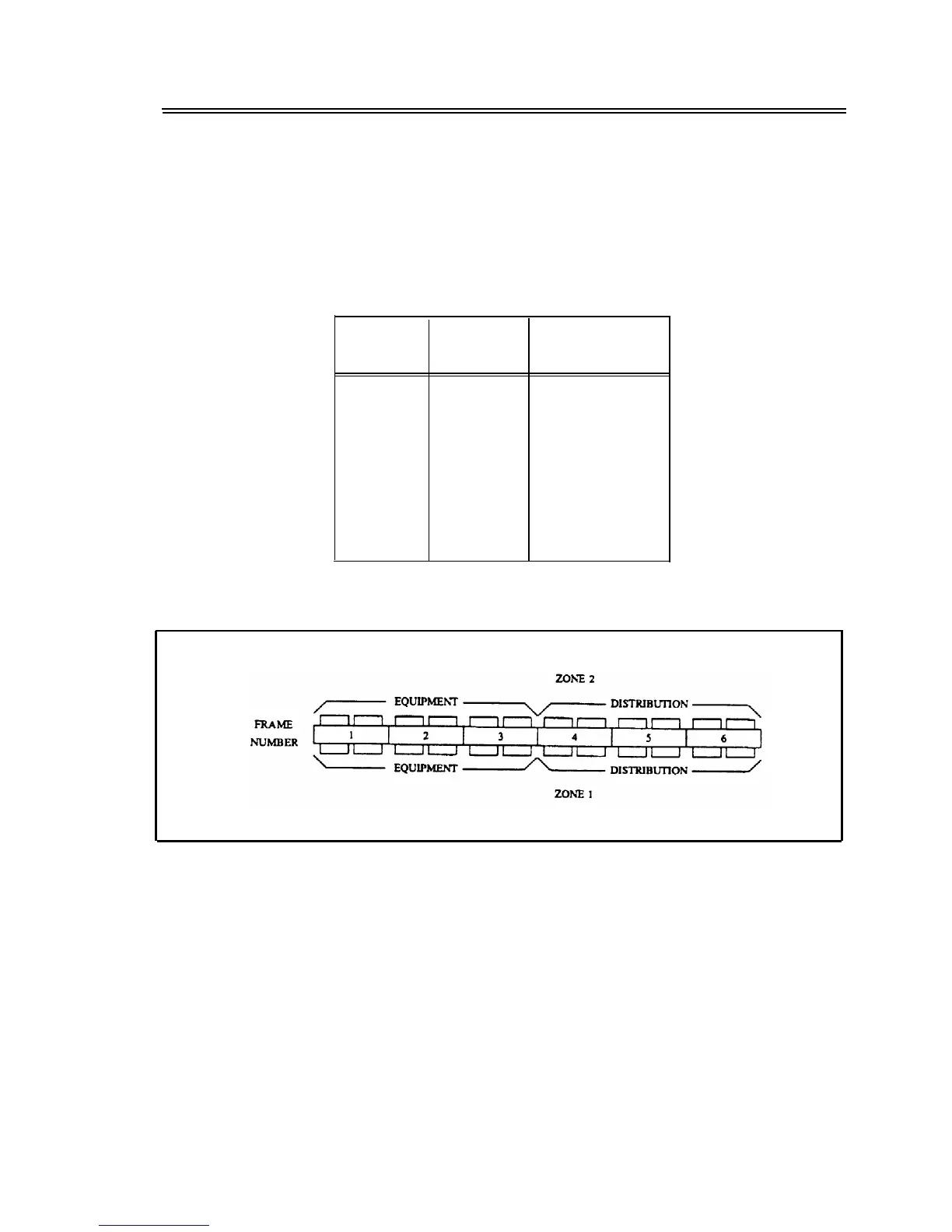
type-2 frame. Each type-2 frame can accommodate 4000 jumper pairs per side. Figure 7-12,
Zone
Arrangement of Type-2 Frame — Plan View,
and figure 7-13,
Zone Arrangement of Type-2 Frame —
Front View, Zone 2,
show a type-2 frame used in a zone arrangement.
TABLE 7-7. Module Allocation per Zone with Type-2 Frame
Number of
Number of
Number of
Modules
Zones Modules for Zone
1-8
9
10
11
12
13
14
15
16
2
2
1-8
4,5
5,5
5,6
6,6
6,7
2
2
2
2
7,7
2
7,8
2
8,8
NOTE: Custom-engineer all installations over 16 modules.
Figure 7-12. Zone Arrangement of Type-2 Frame — Plan View