5-4
INSTALLATION EXAMPLE: SYSTEM 85 AND DEFINITY GENERIC 2 WITH TRADITIONAL MODULES
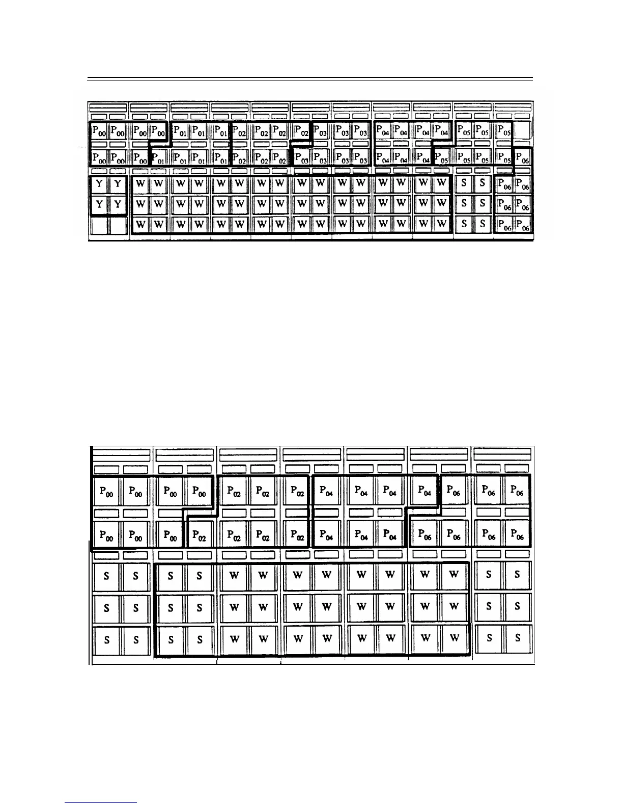
Figure 5-1. 7-Module System Wall-Mounted on Type-1 Frame
Several problems arise from the arrangement shown in figure 5-1,
7-Module System Wall-Mounted
on Type-1 Frame,
that make it undesirable.
First, because the module layouts are asymmetrical,
cable terminations begin in a different location for each module. Second, the layouts for modules 1
through 6 require special frames since each spans three of the type-1 frames. Also, the yellow field
shares the same frame as module 1.
Third, these layouts require jumpers longer than the
recommended 16 ft.
—
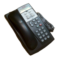
Self-supporting frames.
Mounting the terminal blocks on self-supporting frames, which is preferable
to wall mounting for this installation, requires five type-1 frames or seven type-2 frames. The type-1
frame arrangement is shown in figure 5-2,
7-Module System Mounted on Self-Supporting Type-1
Frame, Front,
and figure 5-3,
7-Module System Mounted on Self-Supporting Type-1 Frame, Rear.
1
I
1
,
Figure 5-2. 7-Module System Mounted on Self-Supporting Type-1 Frame, Front