10 - 2010
5.5.3 Electrical characteristics
•
Voltage of power supply
Table 19: Voltage of power supply of the Hopper
•
Current draw
Table 20: Current draw
5.5.4 Electronic characteristics
Electronic circuit board
The Electronic circuit board of the Hopper is based on a micro-controller with flash memory flash
that allows flash updating of the firmware on site.
To select the ccTalk address of the device and to configure the operation modes, use the block
of 8 dipswitches accessible from the outside.
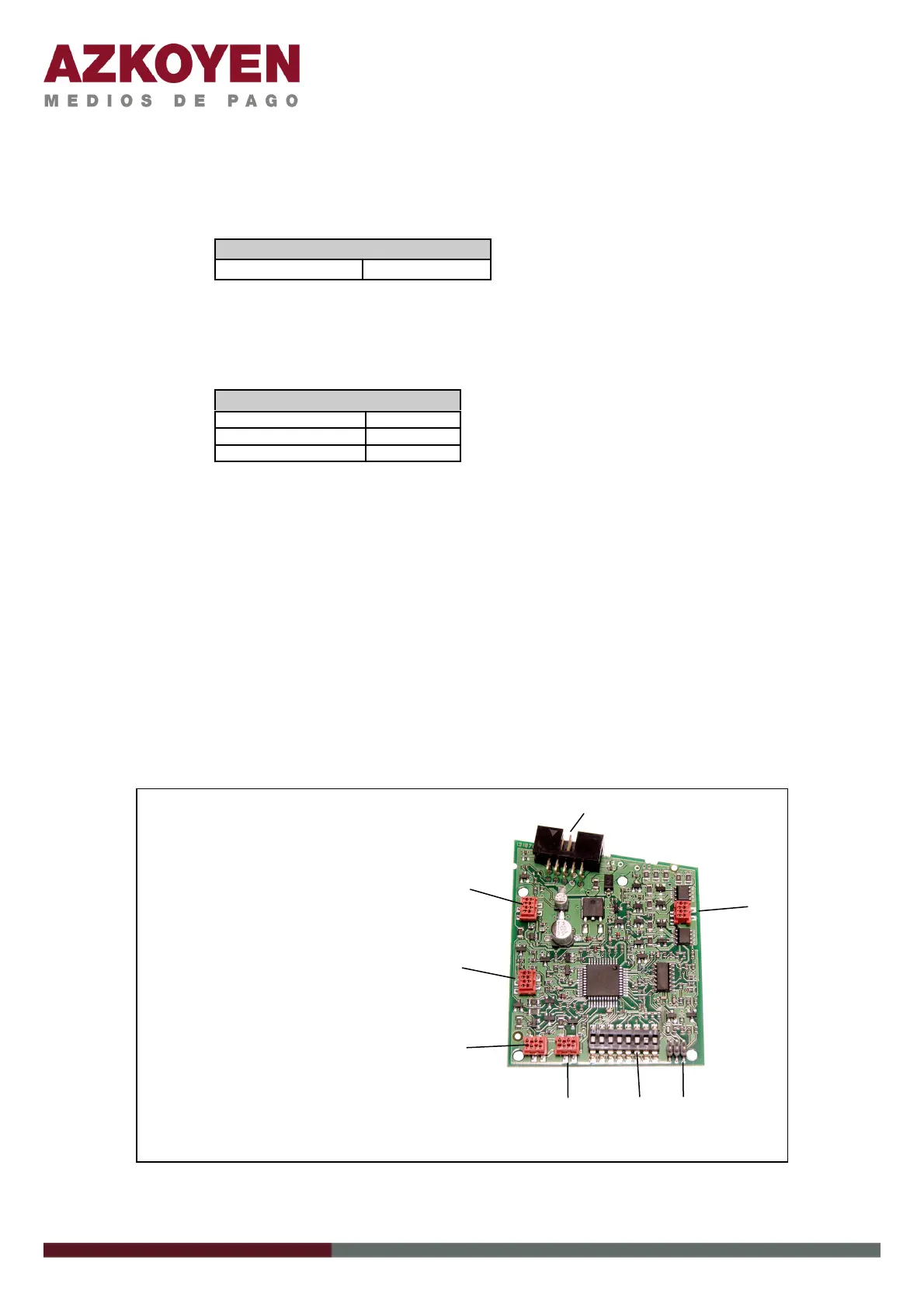
Figure 21: Electronic circuit board Hopper U-II ccTalk
V power supply
Voltage
12-24VDC ± 10%
Current draw
Max. start up
3A ± 20%
standby
50 ma ± 5%
payment
450 mA ± 20%
3
4
5
6
7
8
1
2
1. Q1 – Connection ccTalk
2. Q2 – Motor
3. Q3 – Tools - Azkoyen
4. Dipswitches - configuration
5. Q4 – Sensor - full
6. Q5 – Sensor empty
7. Q6 – Sensor Plus
8. Q7 – Con. Exit sensor
 Loading...