OmniCare EVC System
Installation & Commissioning Manual
OmniCare issue 1
9
C
O
M
M
U
N
I
C
A
T
I
O
N
S
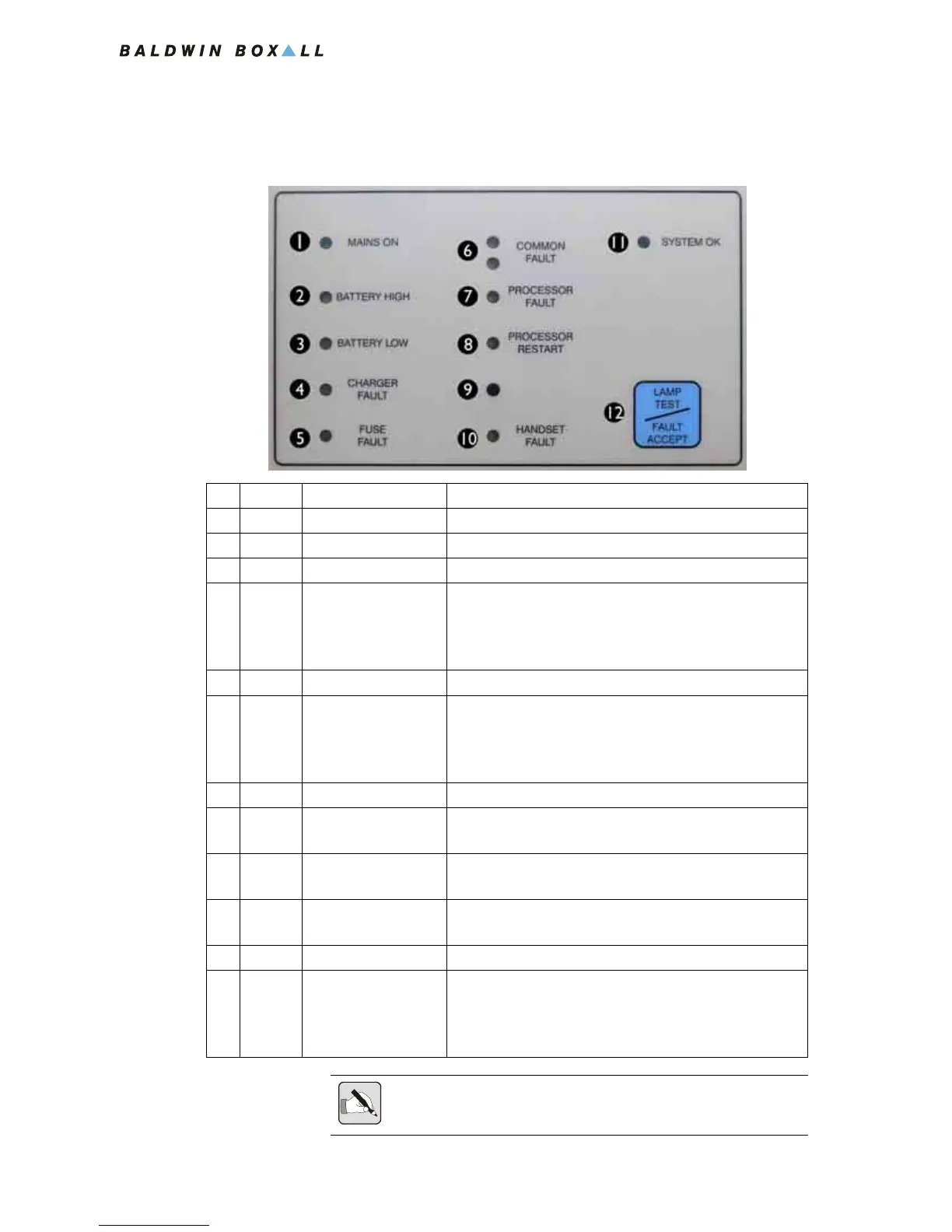
1.3.2 System Status & Fault LEDs
Figure 1.9 — System Status & Fault LEDs
Colour Ident Description
1 Green Mains On Mains supply Connected and Healthy
2 Yellow Battery High Battery Voltage too High (Overcharged) *
3 Yellow Battery Low Battery Voltage too Low (Faulty battery) *
4 Yellow Charger Fault Will illuminate if the batteries are unable to hold their
charge or if they are not fully charged after 24 Hours
charging.
Reset (9) must be pressed to clear a charger fault.
5 Yellow Fuse Fault Will illuminate if any internal DC fuse fails.
6 Yellow Common Fault Will flash and a buzzer will sound when a Fault is
detected until "Fault Accept" (12) is pressed.
After a fault is accepted the buzzer is silenced and the
LEDs remain illuminated until the fault is cleared.
7 Yellow Processor Fault Will illuminate if a critical Processor fault has occurred.
8 Yellow Processor Restart Will illuminate if the Reset Switch (9) needs to be
pressed.
9 N/A Reset Button
(Note - No Ident)
Hidden Switch (with no Ident) that enables the
Processors and Remote Units to be reset.
10 Yellow Handset Fault Will illuminate if a fault is detected with the Control
Unit handset.
11 Green System OK Illuminates when no faults are detected.
12 N/A Lamp Test /
Fault Accept Button
Lamp Test - Press to check all front panel LEDs and
buzzer operation.
Fault Accept - Press to accept a fault and silence the
fault buzzer.
NOTE: * If both the "Battery High" and "Battery Low" fault LEDs are
lit then the batteries are not connected.