10 english
5.1 Installation
NOTICE
Improper installation
Improper installation can compromise the function of the
BTL and result in damage.
► Ensure that no strong electrical or magnetic fields are
present in the direct vicinity of the BTL.
► Be sure to maintain the specified distances and
separations.
For dimensions, see Fig. 4-1 on page8.
Any orientation is permitted. Mount the BTL on a level
surface of the machine using the provided mounting
clamps and cylinder-head screws.
In order to avoid resonant frequencies caused by
vibrations, we recommend positioning the
mounting clamps at irregular intervals.
The magnetostrictive linear position sensor is electrically
isolated from the machine with the supplied insulating
bushes (see Fig. 4-1 on page8).
1. Guide the BTL into the mounting clamps.
2. Attach the BTL to the base using mounting screws
(tighten screws in the clamps with max.2Nm).
3. Install the magnet (accessory).
The magnetostrictive linear position sensor in
profile housing is suitable both for floating, i.e.
non-contacting magnets (see Fig. 5-1 to Fig. 5-8)
and for captive magnets (see Fig. 5-1 and
Fig. 5-2).
5
Installation and connection
5.2 Captive magnets
Note when installing the magnet:
– Avoid lateral forces.
– Connect the magnet to the machine member with a
joint rod (see Accessories on page18).
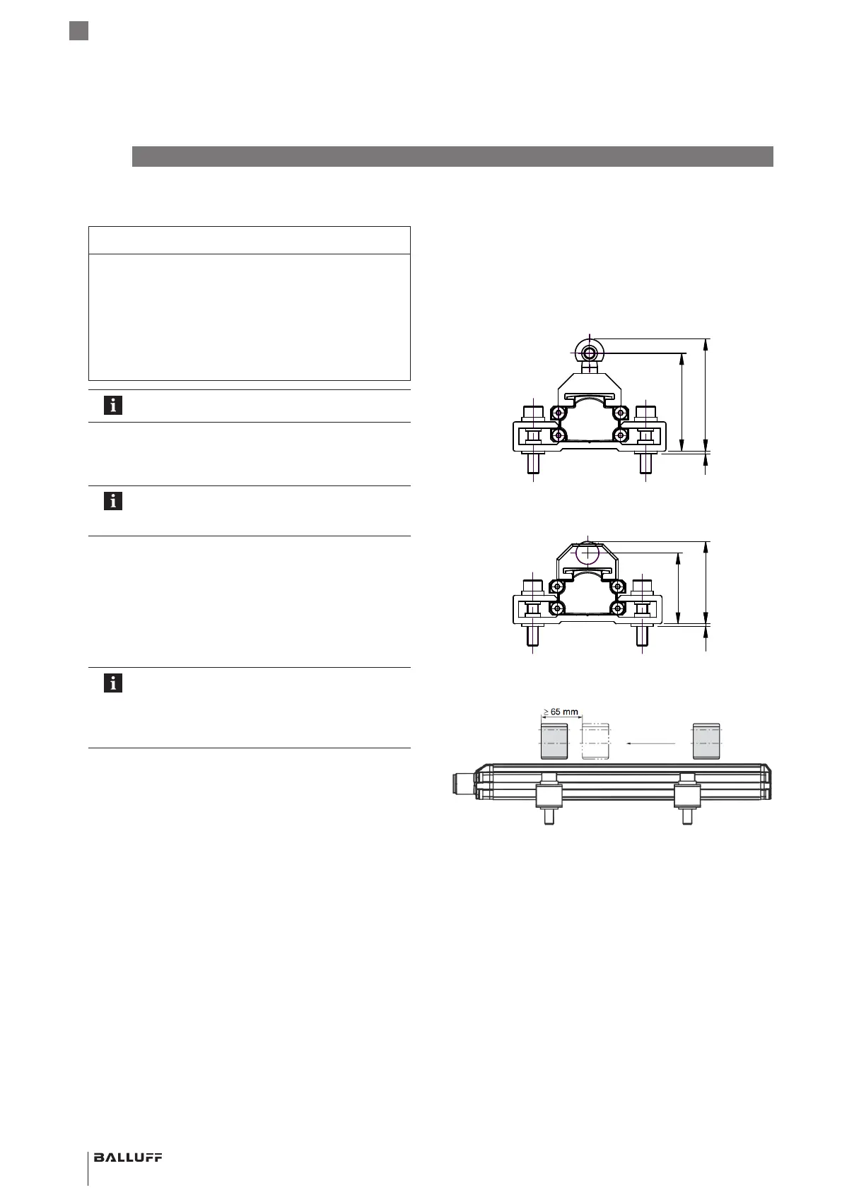
– When using multiple magnets a minimum separation of
65 mm must be maintained between them
(seeFig. 5-3).
Fig. 5-1:
1
44
50.4
Dimensions and spacing with magnet BTL5-F-2814-1S
Fig. 5-2:
1
31.5
36.5
Dimensions and spacing with magnet BTL5-F-2814-1S
Fig. 5-3: Minimum spacing when using multiple magnets
BTL PF _ 400- _ _ _ _ -C12NL _ _ -0-000S04
Magnetostrictive Linear Position Sensor – Profile Style

 Loading...


