10 中文
5.1 安装
注意
错误安装
错误的安装将会导致BTL的功能受到影响,并可能引起
设备损坏。
► 注意BIP周围不能出现强电场或磁场。
► 必须遵守规定的安装距离。
尺寸参见图4-1,第8页。
可选定任意位置安装。通过附带的固定夹和柱头螺丝将
BTL安装于设备的平面上。
为了避免振动负载时共振频率的出现,我们建议
以不规则间隔放置固定夹。
通过附带的绝缘套,实现磁致伸缩位移传感器和机器设备
之间的电绝缘(参见第88页上的ild4-1图4-1)。
1. 将BTL套入夹具中。
2. 通过固定螺丝将BTL固定于底面基座上(用最大2Nm
的力将螺丝拧到固定夹中)。
3. 安装位置指示器(配件)。
采用型材结构的磁致伸缩位移传感器不仅适用于
自由式即非接触工作的位置指示器(参见图5-1
至图5-8),同样也适用于引导性位置指示器(参
见图5-1和图5-2)。
5
安装和连接
5.2 引导性位置指示器
安装位置传感器时务必注意:
– 避免侧向力。
– 将位置指示器通过铰链杆与机器部件连接(参见附
件,第1818页)。
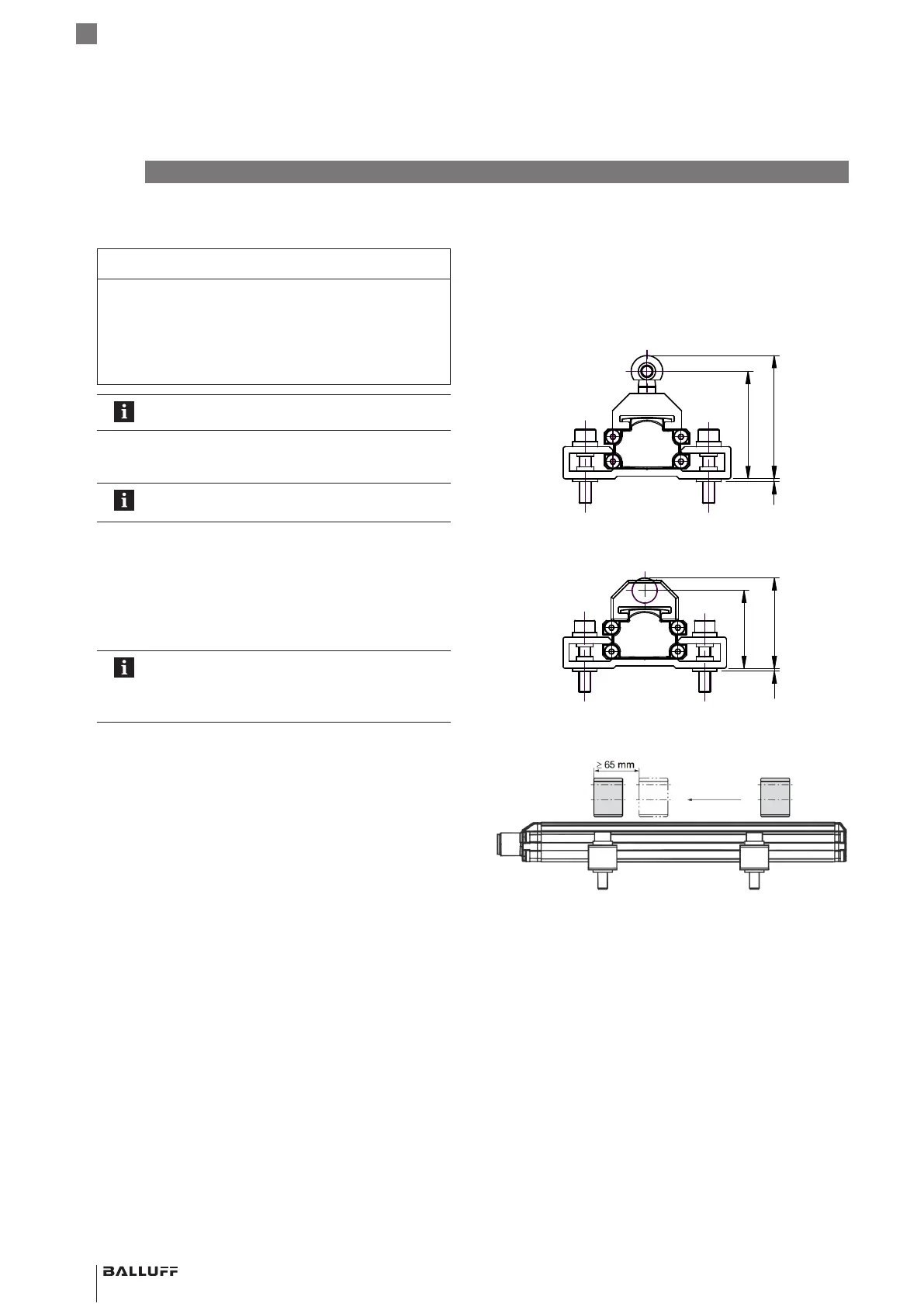
– 使用多个位置指示器时,必须遵守每两个之间的最小
距离65mm(参见图图5-3)。
图5-1:
1
44
50.4
使用位置指示器BTL5-F-2814-1S的尺寸和距离
图5-2:
1
31.5
36.5
使用位置指示器BTL5-F-2814-1S的尺寸和距离
图5-3: 使用多个位置指示器时的最小距离
BTL PF _ 400- _ _ _ _ -C12NL _ _ -0-000S04
磁致伸缩位移传感器–型材结构
 Loading...


