8 english
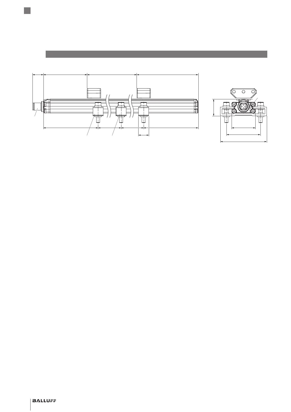
4.1 Construction
Electrical connection: The electrical connection is made
via a connector (see Type code on page20).
Housing: Housing containing the processing electronics.
Magnet: Defines the position to be measured on the
waveguide. Magnets are available in various models and
must be ordered separately (see Accessories on
page18).
Measuring length: Defines the travel/length range
available. Sensors with measuring lengths from 25mm to
4000mm are available.
4
Product description
15
50
68
16
M12
~80 ~80~250 34.8
24.8
~250
70
2)
67
2)
1)
Not included in scope of delivery
2)
Unusable area
3)
Only for BTL PF1400-… included in scope of delivery
Mounting clamps
3)
with insulating bushes and
ISO4762M5x25 cylinder head screws, max. tightening
torque 2Nm
Magnet
BTL5-A-3800-2
1)
Measuring length
Null point End point
LED
Fig. 4-1: Dimensions, design and function
BTL PF _ 400- _ _ _ _ -C12NL _ _ -0-000S04
Magnetostrictive Linear Position Sensor – Profile Style
 Loading...


